
 WhatsApp: +86 16626708626
 Email:
  Phone: +86 16626708626
Description
Key Technical Specifications
| Parameter | Value |
|---|---|
| Manufacturer | Alstom / GE Energy |
| Model Number | L54E1100CZ00 |
| Board Identifier | CPRM1 |
| Control Platform | Microrec K4.1 Digital Excitation System |
| Primary Application | Automatic Voltage Regulator (AVR) / Thyristor Bridge Firing |
| Phase Regulation | High-precision single-phase power regulation loops |
| Backplane Interfacing | Integrates directly with FRTNx carrier frames |
| Isolation Barrier | High-dielectric optoelectronic pulse isolation |
| Logic Synchronization | Synchronized with RDSP1 computing and IRVI20 interface cards |
| Net Weight | 0.68 kg (1.5 lbs) |
| Operating Temperature | 0 to +60 °C inside unventilated excitation cubicles |
| Storage Temperature | −40 to +70 °C |
Product Introduction & Supply Chain Strategy
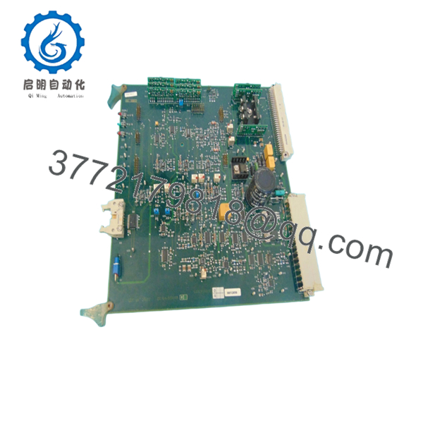
The Alstom L54E1100CZ00 (CPRM1) is a critical single-phase power regulation and thyristor bridge firing card designed for the Microrec K4.1 digital excitation framework. Deployed extensively in utility-scale power plants and industrial cogeneration systems running Alspa P320 systems, this module generates highly accurate, synchronized gating pulses to modulate the thyristor bridges that supply field current to synchronous generators. Working alongside the RDSP1 processing engine, the CPRM1 ensures ultra-low latency response times during load steps, enabling precise stator voltage control, manual excitation limits, and overall grid synchronization.
IEPC Energy
Because the Microrec K4.1 platform was established in the late 1990s and has long since entered obsolescence, the CPRM1 card represents a single point of failure that carries immense lead-time variability risk. Securing this board as a New Surplus unit is a necessary strategic investment to manage the asset’s Total Cost of Ownership (TCO). Relying on refurbished alternatives introduces a dangerous gamble on degraded pulsing transformers or failing gate-drive logic. A single breakdown here can cause a full generator trip, translating a minor procurement savings into hundreds of thousands of dollars in unpredicted offline losses.

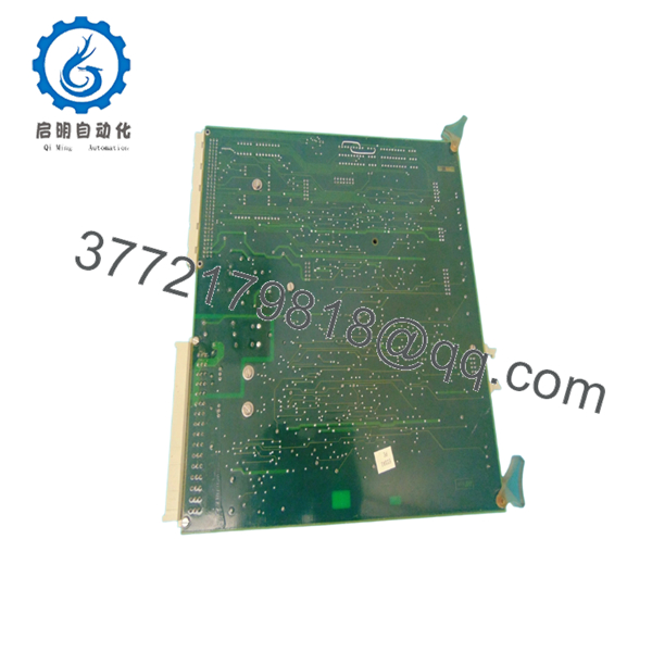
- L54E1100CZ00 Microrec K4.1
- L54E1100CZ00 Microrec K4.1
Installation & Configuration Guide
Stage 1: Pre-Installation (Prep & Safety)
- Initiate strict site lock-out/tag-out (LOTO) commands on both the low-voltage control rack supply and the main high-voltage excitation transformer inputs.
- Verify with a calibrated high-voltage proximity tester that the main thyristor bridge bus bars are completely de-energized.
- Fasten a grounded ESD wrist strap to your arm and connect the line to an unpainted chassis earth point.
- Document the exact slot location on the FRTNx backplane and capture high-resolution images of any on-board jumper links or socketed chip orientations.
Stage 2: Removal
- Loosen the upper and lower faceplate captive locking screws anchoring the L54E1100CZ00 card to the system rack.
- Disconnect any front-facing pulse transmission ribbon cables or diagnostic leads, noting their exact pin orientations.
- Use steady, parallel horizontal force to slide the board outward along its chassis guide tracks. Avoid any vertical twisting to prevent scoring adjacent circuit board tracks or snapping rear backplane contacts.
- Put the extracted assembly directly into an ESD-shielded anti-static bag.
Stage 3: Installation (Clone & Seat)
- Open the new surplus L54E1100CZ00 board inside an ESD-protected clean zone.
- Match all physical jumper blocks and trace elements on the incoming CPRM1 board to ensure it completely mirrors the configuration of the original module.
- Slide the card smoothly through the guide rails until the backplane plug matches up with the main system bus. Press firmly until the board locks flush into position.
- Tighten the faceplate screws to establish frame ground pathing and secure the front signal connections.
Stage 4: Power-On & Testing
- Verify the logic power supply levels to make sure they match target system documentation.
- Re-energize the Microrec control rack, keeping the main high-voltage excitation power isolated for safety.
- Watch the diagnostic indicator array: ensure that initial power-on self-tests complete cleanly, showing active logic status without triggering any firing circuit failure faults.
- Run standard gate pulse validation testing using an oscilloscope at the test points to confirm stable pulse generation and clear synchronization before restoring the high-voltage thyristor line.
Firmware/Software Versions & Upgrade Notes
The Microrec K4.1 L54E1100CZ00 card handles hardware-level pulse regulation and relies on the exact timing definitions embedded within its on-board logic components and the host RDSP1 processing card. System modifications are generally carried out via proprietary XS103 or XS106 engineering software tools.
IEPC Energy
When installing a replacement CPRM1 board, avoid altering the core parameter database or making configuration updates during emergency recovery operations. Mismatched timing profiles or unsynchronized firing algorithms between redundant channels will cause immediate changeover faults, preventing the automatic voltage regulator (AVR) from switching channels cleanly during a transient event. Always match the hardware revision code stamped on your original card before approving full loop operation.
Frequently Asked Questions (FAQ)
Q: What is the primary operational distinction between the CPRM1 board and other Microrec cards like the CPRTx? A: The CPRM1 is explicitly optimized as a single-phase power regulation and thyristor firing card, running high-speed gating routines directly linked to power bridge regulation. While the wider CPRTx series covers a broader array of multiphase excitation bridges, the CPRM1 provides dedicated single-phase pulse control channels for specific specialized thyristor designs utilized in legacy Alstom generator setups.
Q: Why should our plant invest in a New Surplus board instead of a much cheaper used/refurbished unit? A: Excitation modules, particularly thyristor firing cards like the CPRM1, operate in high thermal environments and drive continuous pulse current loops. Refurbished units are typically salvage parts that have already accumulated years of thermal stress, which degrades internal capacitors, pulse transformers, and optocouplers. Buying a New Surplus card ensures zero component wear and an untouched manufacturing lifespan, minimizing the hazard of unexpected trips and lowering your plant’s overall Total Cost of Ownership (TCO).
Q: Is this card fully interchangeable across Microrec K4.0, K4.1, and K4.2 systems? A: This specific L54E1100CZ00 card is engineered for the Microrec K4.1 digital architecture. While the overall excitation series shares structural concepts, shifting across different platform baselines (like K4.0 to K4.1) can cause physical pin-out changes or backplane timing mismatches. Always match the model number and the CPRM1 code directly to ensure complete drop-in compatibility.
Q: Can this power regulation card be replaced while the generator excitation system is running on the backup channel? A: If your Microrec K4.1 setup is configured as a fully dual-channel redundant system, it is theoretically possible to swap an inactive card while the other channel handles load control. However, this hot-swap should only be carried out under strict engineering oversight. Sledding a card into an active backplane can cause transient voltage drops on the common power bus, risking an accidental trip of the active channel if not done carefully. Shutting down the cabinet completely during an outage is the safest route.
Q: What type of warranty backing is provided for this legacy Alstom card? A: Since the original equipment manufacturer long ago wrapped up factory production and direct lifecycle support for this series, factory warranties are unavailable. To ensure your asset reliability, we cover this genuine New Surplus L54E1100CZ00 card with our own comprehensive 2-year warranty that protects against all mechanical component failures and functional electrical defects.



