
 WhatsApp: +86 16626708626
 Email:
  Phone: +86 16626708626
Description
3. Key Technical Specifications
| Parameter | Value |
|---|---|
| Manufacturer | ALSTOM / Cegelec Controls Ltd. |
| Model Number | MAE00-07 |
| System Compatibility | ALSPA Drive and Automation Networks |
| Module Type | Dedicated Field Terminal Interface |
| Logic Nominal Voltage | +24 V DC |
| Operational Voltage Range | 0 V to +30 V DC max |
| Input Channels | Multi-point high-density terminal layout |
| Signal Isolation | Integrated optocoupler barrier pathways |
| Terminal Connection | Heavy-duty screw clamp interfaces |
| Mounting Profile | Standard sub-panel chassis or DIN rail frame assembly |
| Primary Protection | Transient surge suppression and ground-loop isolation |
4. Product Introduction & Supply Chain Strategy
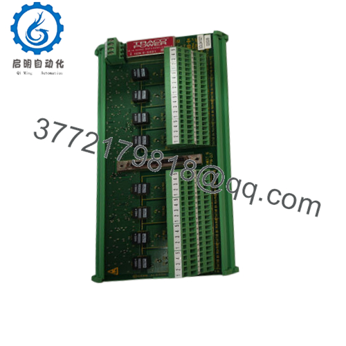
The ALSTOM MAE00-07 is a high-reliability Digital Input Termination Panel designed for legacy Cegelec and ALSTOM ALSPA drive control systems. Operating as a critical hardware buffer, this card provides the physical landing point for 24 V DC discrete field signals—such as limit switches, proximity sensors, and auxiliary interlocks—before they interact with sensitive core processing units. It conditions noisy incoming field lines using optoelectronic isolation and surge-suppression components, blocking electromagnetic interference (EMI) and preventing inductive voltage spikes from damaging the system’s central logic rack.
From an engineering and procurement asset standpoint, stocking this discontinued component as a New Surplus asset is vital for protecting plant infrastructure. When a field short-circuit or lighting strike overloads a terminal block, the termination panel acts as an sacrificial barrier to shield upper-level processors. Because the ALSPA legacy platform is obsolete, a failure here can stall operations if a replacement board is unavailable. Choosing a verified New Surplus MAE00-07 avoids the unpredictable trace corrosion, heat fatigue, and loose terminal blocks common to refurbished hardware, stabilizing your Total Cost of Ownership (TCO) and securing your field-to-logic interfaces.

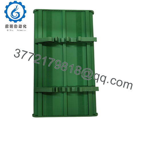
- MAE00-07
5. Installation & Configuration Guide
Stage 1: Pre-Installation (Prep & Safety)
- De-energize the entire control enclosure. Confirm that both the main system logic power and the external +24 V DC field wetting voltages are locked out and tagged out (LOTO).
- Use a calibrated digital multimeter to verify that no residual voltage is present on any input screw terminals.
- Secure a grounded electrostatic discharge (ESD) wrist strap around your wrist, connecting the clamp to the unpainted chassis frame.
- Clearly label all landing wires with their corresponding channel numbers, and take high-resolution reference photos of the wire routing configuration.
Stage 2: Removal
- Systematically loosen the screw clamp terminals and back out the external field input wires.
- Disconnect the main ribbon data harness or serial interface cable that links this termination module to the processing card cage.
- Remove the retaining screws or disengage the locking tabs that anchor the card frame to the sub-panel or DIN mounting system. Lift the board away safely.
Stage 3: Installation (Clone & Seat)
- Inspect the New Surplus ALSTOM MAE00-07 panel for any storage or shipping damage.
- Verify that any on-board jumper links, isolation switches, or grounding bars are configured identically to the module you just removed.
- Snap the new panel firmly onto the chassis DIN rail or screw it tightly into the mounting panel to ensure a secure mechanical ground.
- Plug the master interface data harness back into its socket, ensuring that the connector alignment pins seat squarely.
- Re-terminate all 24 V DC field input lines into their designated screw channels based on your wiring diagrams.
Stage 4: Power-On & Testing
- Re-apply the primary logic power and external +24 V DC field sensing voltages to the enclosure panel.
- Measure the input supply voltage across the main rails to confirm it stays within the designated operational limits (0 V to +24 V DC).
- Activate the connected field inputs one at a time (e.g., tripping a limit switch) and monitor the on-board status LEDs or processing indicators to verify accurate signal transmission.
6. Firmware/Software Versions & Upgrade Notes
The ALSTOM MAE00-07 is an unmanaged hardware interface board made up of terminal blocks, passive components, and optocouplers. It does not contain programmable microprocessors, flash memories, or updateable firmware kernels.
However, because circuit layouts and channel impedances vary by revision number, you must match the exact “MAE00-07” part designation during replacement. Substituting this board with an earlier variant or an alternative analog termination board can alter input impedance thresholds, leading to signal drops, missing logic states, or timing lags within the ALSPA control framework.
7. Frequently Asked Questions (FAQ)
- Why is buying a New Surplus MAE00-07 better than a refurbished alternative? Termination panels are exposed to physical mechanical stress from repeated terminal torque, as well as voltage spikes from field wiring. Refurbished units often look clean but may harbor microscopic cracks in their solder joints or weakened optocouplers that fail under real-world loads. This New Surplus board provides pristine, zero-hour circuits that deliver original OEM reliability from day one.
- Does this panel include its own internal power generation for the 24V inputs? No. The MAE00-07 distributes and conditions external power loops, but it requires an external source to provide the necessary +24 V DC wetting voltage to sense incoming field signals.
- Can this panel handle analog inputs, such as 4–20 mA current loops? No. This specific board is configured explicitly as a digital (discrete) input termination panel. It is tailored for standard on/off signals and cannot process continuous analog data streams. For analog setups, you will need a dedicated module, such as the MAE00-05.
- What is the common cause of failure on these termination panels? Over-tightening terminal screws, which can fracture internal PCB copper traces, and high-voltage field surges that exceed the optocoupler isolation limits are the two most common causes of failure. Always use calibrated tools and stay within the specified operating voltage range.
- Can I wire or change connections while the system power is active? No. Working on the module while it is energized can lead to accidental short circuits between adjacent terminal channels. This can cause high-voltage backfeeding into the data harness, risking permanent damage to the primary processor modules. Always isolate power before making wiring adjustments.
- What type of warranty coverage comes with this New Surplus board? We include a comprehensive 1-year replacement warranty on this module. This guarantees that your hardware will drop in seamlessly and perform to factory specifications, protecting your legacy asset infrastructure from unexpected system downtime.



