WhatsApp: +86 16626708626
 Email:
 Phone: +86 16626708626
Description
Key Technical Specifications
| Parameter | Value |
|---|---|
| Model | MAE99-04 |
| Manufacturer | Alstom (Power Conversion) |
| Product type | 8-channel serial interface isolation unit |
| Number of channels | 8, independently isolated per channel |
| Supply voltage | 18–30 V DC, dual redundant power input |
| Galvanic isolation | Per-channel isolation barrier (verify exact isolation voltage against the OEM datasheet before installation) |
| Diagnostics | Per-channel transmit/receive status LEDs |
| Mounting | 35 mm DIN rail |
| Operating temperature | Typically 0 °C to +60 °C (confirm rating for your revision) |
| Protocols supported | Serial point-to-point links within rated electrical limits (e.g., RS-232/RS-422/RS-485-class lines — confirm against your system documentation) |
| Dimensions / weight | Compact rail-mounted enclosure; confirm exact figures on unit label |
| Condition | New Original / New Surplus, tested |
| Warranty | 12 months |
Note: The MAE99-04 was never a high-volume catalog item, and public documentation is thin. Alstom (now part of GE Vernova / Alstom S.A. depending on division) did not publish a widely circulated datasheet. Verify channel wiring and voltage ratings against your installation manual or the nameplate before energizing.
Product Introduction
The Alstom MAE99-04 is an 8-channel serial interface isolation unit used in power plant automation, turbomachinery control, and grid protection schemes. Each channel carries its own galvanic isolation barrier, which blocks ground loops, surge energy, and high-frequency interference from reaching controllers and CPUs downstream.
Plants keep this module as a spare because it sits between expensive logic devices and field cabling. When a surge event or ground fault occurs, the isolation barrier absorbs or fails the fault locally — the MAE99-04 takes the hit instead of the controller. It supports dual redundant 24 V DC feeds, and the per-channel LEDs let a technician confirm link status at a glance without a laptop. The model is discontinued by the manufacturer; availability is limited to new-surplus and tested-refurbished stock.
MAE99-04
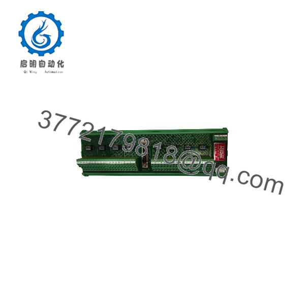
MAE99-04
Installation & Configuration Guide
Stage 1: Pre-Installation Preparation (10 minutes)
⚠️ Safety first. Notify operations of the downtime window. Confirm the affected loop is in a safe state. Lock out/tag out power. Wait 5 minutes for capacitor discharge before touching terminals.
- Tools: grounded ESD wrist strap, PH1 screwdriver, Fluke 115-class multimeter (or better), wire labels, smartphone for photos.
- Data backup: photograph the existing module front panel, terminal wiring, and any DIP switches or jumpers. Record channel assignments on paper. Do not rely on memory — 8 channels of mixed point-to-point wiring is easy to cross.
Stage 2: Removing the Old Module (5–10 minutes)
- Remove the front cover/bezel if fitted.
- Label each conductor, then disconnect wiring. Do not force terminal screws — a stripped terminal block on this vintage hardware means hunting for a replacement carrier.
- Release the DIN-rail clip and pull the unit straight off the rail.
- Inspect the rail area for dust, corrosion, or loose hardware.
⚠️ Keep the old module on the bench until the replacement has run clean for a full shift. If the replacement has a fault, you’ll want the original for comparison.
Stage 3: Installing the New Module (10 minutes)
- Ground yourself with the ESD strap before unpacking the unit.
- Verify the nameplate reads MAE99-04 — the MAE99 family includes multiple variants (e.g., MAE99-01 with fewer channels) that look similar.
- Replicate any switch/jumper settings from your photos. This module has few configurable items, but if your unit has an address or termination setting, mirror it exactly.
- Snap the unit onto the 35 mm DIN rail and torque terminal screws to the manufacturer’s spec (typically 0.5–0.6 N·m for this class of terminal — snug, not stripped).
- Separate input-side and output-side cabling into different bundles or conduits. Routing both sides through the same conduit degrades the isolation barrier’s effectiveness and can reintroduce the coupling you installed the module to prevent.
Self-check: [ ] Model verified · [ ] Wiring matches photos · [ ] Input/output cables separated · [ ] Ground connected per wiring diagram only (one point — do not create a second ground path).
Stage 4: Power-On & Testing (10–15 minutes)
- Before energizing, measure resistance across the 24 V DC supply terminals with the module connected. A dead short means stop and investigate.
- Power the module only, with field devices disconnected if your procedure allows it.
- Confirm the power LED. Then reconnect field circuits one channel at a time, watching the per-channel TX/RX LEDs.
- Verify data flow at the host end (terminal emulator or system diagnostic page) for each restored link.
- Log the serial number and install date in your maintenance record.
⚠️ If a channel shows RX activity but no TX (or vice versa), suspect a swapped TX/RX pair at the terminal — check against your photos before assuming module failure. If the module refuses to power on one redundant input but runs on the other, the redundant feed is wired backwards or the second supply is down; the module will run, but you’ve silently lost redundancy.
Frequently Asked Questions
Q: Can I hot-swap this module under power?
No. This is not a hot-swap device. Pulling it live on a serial link can dump transients onto the lines and, on shared supplies, disturb adjacent cards. Kill the power, isolate the loop, and swap it cold. If your application genuinely cannot tolerate the outage, plan a changeover window — don’t gamble with the backplane.
Q: Is this model obsolete, and is it genuinely new?
Yes, it’s discontinued by the manufacturer, so OEM channel stock is gone. What remains on the market is new surplus (factory-sealed units from plant inventories and distributor dead stock) and refurbished units pulled from decommissioned systems. We state the exact condition per unit — New Original (New Surplus) or Refurbished (tested) — on the quotation. Ask for photos of the actual unit and the test report before you commit.
Q: What’s the direct replacement if this is out of stock?
There is no drop-in successor part number from Alstom for the MAE99-04. Practical options: the MAE99-01 variant for installations needing fewer channels (verify channel count and pinout first), or an external industrial isolator (e.g., a rail-mount serial isolator from Weidmüller or Phoenix Contact) rewired into the same function. Both require engineering review — this is not a like-for-like swap, so budget commissioning time.
Q: Will pulling the old module lose my configuration?
No. The MAE99-04 has no stored program or database — it’s a passive-to-semi-active isolation device. Configuration lives in your controllers, not here. The only settings to preserve are physical: DIP switches, jumpers, and wiring. Photograph them before removal; that photo is your configuration backup.
Q: Why is your price lower than OEM list price?
Because the OEM list price is a historical number for a product the manufacturer no longer sells. Surplus stock comes from closed plants, cancelled projects, and distributor liquidation — we buy below list and price accordingly. The trade-off is honesty about condition: a 2010s-vintage new-surplus unit may have aged electrolytic capacitors. Ours are power-on tested under load for 24 hours before shipment, with insulation resistance verified on a 500 V Megger (>10 MΩ). Test videos and photos are available on request.
Q: How do I verify I’m getting a genuine unit and not a counterfeit?
Check the nameplate printing quality, serial number consistency, and housing mold marks against any reference unit you have. We verify every inbound unit against OEM packing lists or customs declarations, log serial numbers, and reject anything with rework marks, corrosion, or UV-yellowed housings. If you have a working unit on site, send us its serial prefix and we’ll confirm the batch matches before shipping.