
 WhatsApp: +86 16626708626
 Email:
  Phone: +86 16626708626
Description
3. Key Technical Specifications
| Parameter | Value |
|---|---|
| Manufacturer | ALSTOM / GEC Alsthom |
| Model Number | MAVS02L1BD0751D |
| Product Type | Check Synchronising Relay |
| Series | MAVS 01 / MAVS 02 / MAVS 03 Relay Family |
| Main Function | Synchronism checking before breaker closing |
| Measurement Functions | Phase angle difference, slip frequency, differential voltage blocking |
| Application | Generator synchronization and electrical protection systems |
| Mounting Type | Panel-mounted protection relay case |
| Auxiliary Supply | Verify exact variant from relay nameplate |
| Voltage Range | Verify relay configuration code before installation |
| Frequency | 50/60 Hz system dependent |
| Condition Available | New Original (New Surplus) or Refurbished (tested) |
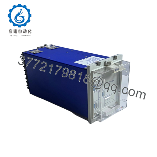
The ALSTOM MAVS relay family is used for check synchronising applications. MAVS02 variants measure phase angle difference and slip frequency while providing differential voltage blocking functions before allowing breaker closing. Inventory references identify MAVS02D1AB0751D as a GEC Alsthom/ALSTOM MAVS protection relay variant.
4. Product Introduction
ALSTOM MAVS02L1BD0751D is a MAVS check synchronising relay designed for electrical protection systems where controlled circuit breaker closing requires verification of synchronised voltage conditions. It is used in generator, substation, and power distribution applications.
For replacement work, engineers should verify the complete ordering code, auxiliary supply, voltage transformer inputs, contact configuration, and existing protection settings. Relay code variations can change electrical parameters, so replacement by appearance alone is not recommended.

- MAVS02L1BD0751D
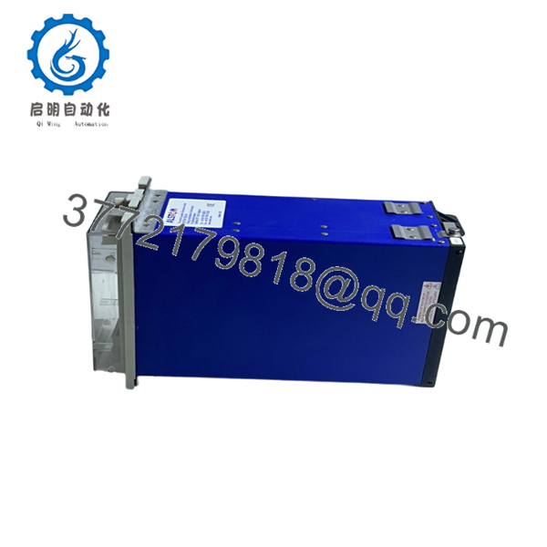
- MAVS02L1BD0751D
5. Installation & Configuration Guide
Stage 1: Pre-Installation Preparation (Estimated Time: 10–15 minutes)
⚠️ Safety First:
- Notify operations before removing the relay.
- Confirm the breaker/control circuit is in a safe maintenance condition.
- Apply lockout/tagout procedures.
- Isolate control power and verify absence of voltage.
- Wait at least 5 minutes for stored energy discharge.
Tools Required:
- ESD wrist strap
- PH1 screwdriver
- Fluke 115 multimeter
- Insulated hand tools
- Wire labels
- Smartphone/camera for documentation
Data Backup:
- Record relay front label details.
- Photograph all terminal wiring.
- Document CT/PT or VT connection points.
- Record existing relay settings:
- Phase angle limits
- Slip frequency settings
- Voltage blocking settings
- Timer settings
- Save commissioning records if available.
Stage 2: Removing the Old Module (Estimated Time: 10 minutes)
- Remove relay panel cover if installed.
- Label every terminal connection.
- Disconnect control wiring carefully.
- Remove relay mounting hardware.
- Withdraw the MAVS relay from the panel.
- Inspect terminal blocks and wiring condition.
⚠️ Note: Keep the original relay until the replacement passes functional checks. Protection settings are often the missing piece during emergency replacements.
Stage 3: Installing the New Module (Estimated Time: 15 minutes)
- ESD Preparation: Wear a grounded wrist strap before handling the relay electronics.
- Verify:
- ALSTOM marking
- MAVS02L1BD0751D part number
- Hardware identification
- Configuration Clone (Critical):
- Copy all relay settings from the original unit.
- Match VT input configuration.
- Confirm auxiliary supply rating.
- Verify output contact assignment.
- Mount the relay into the panel.
- Reconnect wiring according to the documented terminal diagram.
- Tighten terminals correctly.
Self-Checklist:
- Part number verified
- Auxiliary supply confirmed
- VT inputs matched
- Protection settings copied
- Terminals secured
Stage 4: Power-On & Testing (Estimated Time: 20–30 minutes)
Pre-Power Check:
- Use a Fluke 115 multimeter to verify correct auxiliary supply.
- Confirm no wiring short exists.
- Check grounding continuity.
Power-On Steps:
- Energize relay auxiliary supply only.
- Confirm LED/status indication.
- Verify relay self-check status.
- Apply simulated voltage inputs if test equipment is available.
- Verify:
- Phase angle measurement
- Slip frequency response
- Voltage blocking function
- Output relay operation
- Restore the breaker control circuit after successful testing.
⚠️ Troubleshooting Note:
If the relay does not permit synchronising, check VT polarity, phase rotation, incorrect settings, and auxiliary supply first. A relay can appear healthy while measuring incorrect field references.
6. Frequently Asked Questions (FAQ)
Q: Can I hot-swap the ALSTOM MAVS02L1BD0751D relay?
A: No. Protection relays should not be removed under live conditions unless the specific switchgear design permits it. Isolate auxiliary power and verify safe conditions before replacement.
Q: Is the ALSTOM MAVS02L1BD0751D obsolete?
A: The MAVS relay family is a legacy protection platform. Availability is generally through remaining stock, surplus inventory, or tested refurbished units. Replacement planning should include setting verification and commissioning time.
Q: Is this a genuine new ALSTOM MAVS02L1BD0751D?
A: Confirm the supply condition before purchase. New Original / New Surplus units should retain original markings and unused condition. Refurbished units should include functional test documentation.
Q: Will I lose relay settings when replacing the MAVS02L1BD0751D?
A: Yes, settings must be transferred manually unless your installation has saved configuration records. Before removal, document every parameter. I have seen commissioning delays because the relay was replaced but the original synchronising limits were not recorded.
Q: What is the direct replacement for MAVS02L1BD0751D?
A: The replacement depends on the protection scheme, VT configuration, contact requirements, and application. Do not replace by relay family name only. Verify the full ordering code and electrical configuration.
Q: Why do protection relay replacements fail after installation?
A: The most common issues are wrong auxiliary voltage, incorrect VT wiring, copied settings errors, and contact mapping differences. A relay can power up normally and still block breaker closing if the measurement inputs are wrong.
Q: What inspection process should be completed before shipping an ALSTOM MAVS02L1BD0751D?
A professional QC process should include:
- Inbound Inspection & Traceability
- Verify source documentation.
- Check relay nameplate and serial number.
- Inspect for corrosion, scratches, rework marks, and mechanical damage.
- Confirm manuals and accessories if available.
- Live Functional Testing
- Test on a suitable protection relay test bench.
- Verify power-up sequence.
- Check LED/status operation.
- Simulate voltage conditions.
- Test relay outputs.
- Generate an official test report.
- Electrical Parameter Testing
- Auxiliary supply verification.
- Insulation resistance testing using a 500 V Megger where applicable.
- Ground continuity check.
- Configuration Verification
- Record relay settings.
- Document hardware revision.
- Photograph front and rear terminal layouts.
- Final QC & Packaging
- QC inspector sign-off.
- Anti-static ESD protection.
- Bubble wrap and heavy-duty corrugated packaging.
- QC Passed label with inspection date.
Test photos and videos should be available upon request. Verified functional testing under controlled conditions is the appropriate standard for legacy protection relay replacements.



