
 WhatsApp: +86 16626708626
 Email:
  Phone: +86 16626708626
Description
3. Key Technical Specifications
- Part Number: MMLG01
- Manufacturer: ALSTOM / GE Grid Solutions
- Product Type: Standard Test Block Module
- Series: Midos Protection Relay System
- Main Function: Provides safe isolation and testing access for protection relay circuits
- Circuit Count: 14 individual test circuits
- Compatible Test Plug: MMLB01 multi-finger test plug
- Rated Supply Voltage: 24 V DC (listed specification)
- Supply Voltage Range: 21.6 V DC to 26.4 V DC (listed specification)
- Power Consumption: <1 W (listed specification)
- Isolation Voltage: ≥1,000 V AC (listed specification)
- Weight: Approx. 1.32 kg
4. Product Introduction
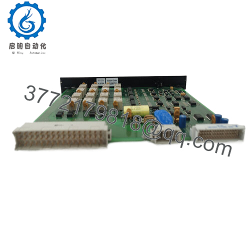
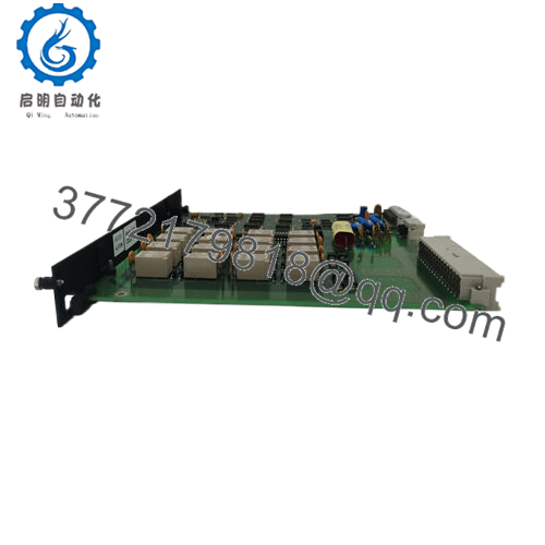
The ALSTOM MMLG01 is a Midos series relay test block module used in electrical protection systems. It provides a permanent interface between protection relay wiring and external test equipment, allowing monitoring and secondary injection testing without removing field wiring.
This module is typically installed in protection relay panels for substations and industrial power systems. Before replacement, verify the exact MMLG01 variant, rear terminal arrangement, and compatibility with the installed relay test plug system.

- MMLG01
5. Installation & Configuration Guide
Stage 1: Pre-Installation Preparation (Approx. 15 minutes)
⚠️ Safety First
- Notify operations before working on the protection panel.
- Place the protected equipment into a safe maintenance condition.
- Apply lockout/tagout procedures where required.
- Isolate auxiliary/control power.
- Confirm the circuit is safe before removing the test block.
Tools Required
- ESD wrist strap
- PH1 screwdriver
- Digital multimeter
- Wire labels
- Smartphone for photos
- Terminal screwdriver
Data Backup
- Record the installed module marking: ALSTOM MMLG01.
- Photograph:
- Front test interface
- Rear terminal wiring
- Terminal labels
- Panel location
- Document:
- Relay connections
- CT/VT circuit assignments
- Test wiring arrangement
Stage 2: Removing the Old Module (Approx. 15 minutes)
- Open the protection relay cabinet.
- Identify the existing MMLG01 test block.
- Label all terminal connections.
- Remove wiring carefully without stressing conductors.
- Remove mounting screws/clips.
- Pull the module from the panel.
⚠️ Note: Keep the original module until relay testing confirms the replacement is correct.
Inspect:
- Rear terminals
- Contact condition
- Mechanical damage
- Loose screws
- Signs of overheating
Stage 3: Installing the New Module (Approx. 20 minutes)
- Wear ESD protection before handling the module.
- Confirm the replacement marking matches ALSTOM MMLG01.
- Compare terminal positions with the removed unit.
- Mount the replacement test block.
- Reconnect wiring according to recorded photos.
- Tighten terminals correctly.
Configuration Clone (Critical)
Verify:
- Circuit numbering
- Relay terminal mapping
- Test plug compatibility
- CT/VT isolation arrangement
Self-Checklist
[ ] Correct MMLG01 installed
[ ] Terminal mapping verified
[ ] Mounting secure
[ ] Wiring checked
Stage 4: Power-On & Testing (Approx. 20 minutes)
Pre-Power Check
- Check terminal tightness.
- Verify no accidental short circuits.
- Confirm protection circuit wiring.
Power-On Steps
- Restore auxiliary supply if applicable.
- Confirm relay panel status.
- Insert the correct MMLB01 test plug when required.
- Perform secondary injection testing.
- Verify relay trip and alarm circuits.
⚠️ Troubleshooting Note
- Test circuit open: Check rear terminal wiring.
- Relay unavailable during testing: Verify test plug insertion and contact operation.
- Incorrect protection response: Confirm circuit mapping before testing.
6. Frequently Asked Questions (FAQ)
Q1: What is the ALSTOM MMLG01 used for?
The MMLG01 is a protection relay test block module. It allows technicians to isolate and test relay circuits using a compatible test plug without permanently disturbing the protection wiring.
Q2: Is MMLG01 a PLC or DCS module?
No. It is a protection system test interface, not a PLC CPU, I/O module, or DCS controller.
Q3: Can I hot-swap the MMLG01?
No. This module is part of a protection circuit interface. Always follow site procedures and isolate circuits before replacement or testing.
Q4: Does replacing the MMLG01 require programming?
Normally no. The MMLG01 is a passive test interface module. The main task is correct wiring transfer and circuit verification.
Q5: What test equipment works with MMLG01?
The module is designed for use with the MMLB01 multi-finger test plug for relay testing applications.
Q6: Why is MMLG01 still purchased if it is an older part?
Many substations and industrial plants keep installed ALSTOM Midos protection systems in service. Maintaining the original test interface can avoid larger protection panel modifications.
Q7: What should I verify before ordering?
Confirm:
- Exact model: MMLG01
- Full variant code if available
- Rear terminal layout
- Existing relay panel design
- Test plug compatibility
- Condition: New Original, New Surplus, or Refurbished
A correct model number is important, but terminal configuration must also match the installed protection scheme.



