
 WhatsApp: +86 16626708626
 Email:
  Phone: +86 16626708626
Description
3. Key Technical Specifications
- Manufacturer: Alstom
- Model: N895313512X
- Product Type: Industrial Control Module / Controller Unit
- Main Function: Control processing, signal handling, and system coordination
- Application: Alstom automation, power control, and legacy industrial systems
- Architecture: Modular electronic control hardware
- Mounting Type: Rack or panel-mounted installation (system dependent)
- Communication Interface: System dependent; verify installed platform documentation before replacement
- Power Supply: Configuration dependent; verify module label and technical drawing
- Operating Environment: Industrial control cabinet environment
- Related References: N95313012D / SUP-AL / N895313000R appear in aftermarket references as associated Alstom modules.
- Lifecycle Status: Legacy spare component; availability depends on remaining inventory.
4. Product Introduction
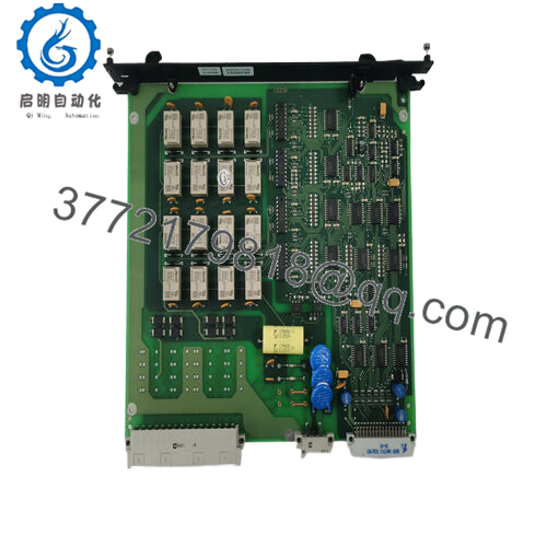
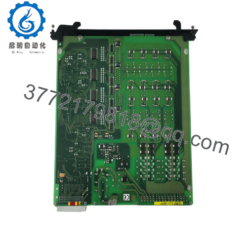
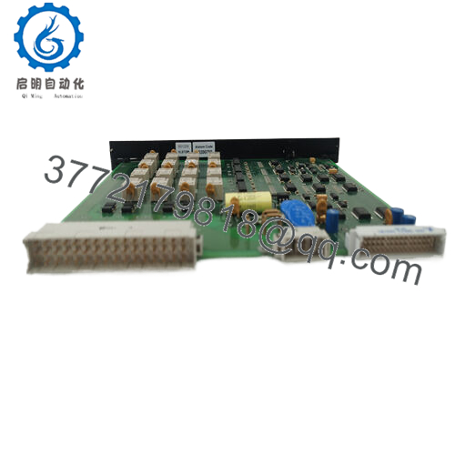
The Alstom N895313512X is an industrial control module used in legacy Alstom automation and power control systems. It is referenced in aftermarket documentation as a controller-type module associated with Alstom control architectures, including applications in power and industrial automation environments.
This module is typically supplied for maintenance replacement where existing Alstom control hardware remains operational. Before installation, verify the complete part number, hardware revision, rack location, connector layout, and original system configuration.

- N895313512X
5. Installation & Configuration Guide
Stage 1: Pre-Installation Preparation (Approx. 10 minutes)
⚠️ Safety First
- Notify operations about the planned maintenance activity.
- Confirm the equipment is in a safe shutdown condition.
- Apply lockout/tagout procedures.
- Remove cabinet power.
- Wait for stored energy discharge before handling the module.
Tools Required
- ESD wrist strap
- PH1 screwdriver
- Digital multimeter
- Wire labels
- Smartphone/camera for documentation
Data Backup
- Record the existing N895313512X installation position.
- Photograph:
- Module label
- Rack location
- Connector layout
- Adjacent modules
- Document:
- Controller configuration
- Communication settings
- Alarm status
Stage 2: Removing the Old Module (Approx. 10 minutes)
- Open the control cabinet.
- Verify power isolation with a multimeter.
- Label all connectors before removal.
- Disconnect cables carefully.
- Release mounting clips or screws.
- Pull the module straight out.
⚠️ Inspection Note
- Inspect backplane contacts.
- Check for oxidation, contamination, or bent pins.
- Keep the original module until the replacement is fully tested.
Stage 3: Installing the New Module (Approx. 15 minutes)
- Wear ESD protection before handling the replacement.
- Verify:
- Model number: N895313512X
- Hardware revision
- Connector condition
Configuration Clone (Critical)
- Install the module in the same rack position.
- Match:
- Wiring connections
- Address settings
- Hardware switches/jumpers if present
- Controller parameters
- Insert the module into the rack.
- Confirm full seating.
- Secure retaining hardware.
- Reconnect all wiring.
Self Checklist
[ ] Correct N895313512X installed
[ ] Hardware revision checked
[ ] Wiring verified
[ ] Module seated correctly
[ ] Configuration recorded
Stage 4: Power-On & Testing (Approx. 30 minutes)
Pre-Power Check
- Verify supply voltage.
- Check grounding.
- Confirm no wiring short circuits.
Power-On Steps
- Energize control power.
- Observe module status indicators.
- Confirm controller recognition.
- Check system diagnostics.
- Verify communication with the control system.
- Perform functional testing.
⚠️ Troubleshooting Note
- Module not detected: Check rack position, connector seating, and compatibility.
- Communication failure: Verify network parameters and controller configuration.
- Unexpected alarms: Compare firmware/hardware revision with the original module.
6. Frequently Asked Questions (FAQ)
Q1: Can I hot-swap the Alstom N895313512X?
No. Unless the specific Alstom system manual confirms hot replacement, remove power before replacing the module. Legacy controller modules may share backplane power and communication connections.
Q2: Is the Alstom N895313512X obsolete?
The N895313512X is considered a legacy Alstom spare module. Current supply is mainly through remaining industrial inventory and refurbishment channels.
Q3: Is this module new original or refurbished?
Confirm the exact condition before purchase.
Typical categories:
- New Original / New Surplus: Unused OEM inventory.
- Factory Sealed: Original packaging condition.
- Refurbished (tested): Previously installed unit inspected and function tested.
Request label photos, serial information, and test records before installation.
Q4: What systems use the Alstom N895313512X?
The exact application depends on the installed Alstom platform. Market references associate this model with Alstom industrial control and automation systems, including power-related control applications.
Q5: What should I verify before ordering N895313512X?
Check:
- Exact part number
- Hardware revision
- Existing Alstom system model
- Rack position
- Connector type
- Communication configuration
Do not assume another N895313 series module is a direct replacement without verification.
Q6: Will replacing N895313512X erase the control program?
The answer depends on the system architecture. The module may not contain the complete application logic. Back up configuration data and document system parameters before removal.
Q7: What inspection should be completed before installation?
Recommended checks:
- Part number verification
- Serial label inspection
- Visual inspection for corrosion or repair marks
- Connector inspection
- Power-up diagnostic test
- Functional communication test
For critical control systems, request a functional test report before returning the equipment to service.



