
 WhatsApp: +86 16626708626
 Email:
  Phone: +86 16626708626
Description
3. Key Technical Specifications
- Manufacturer: ALSTOM
- Model Number: PIB504
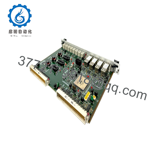
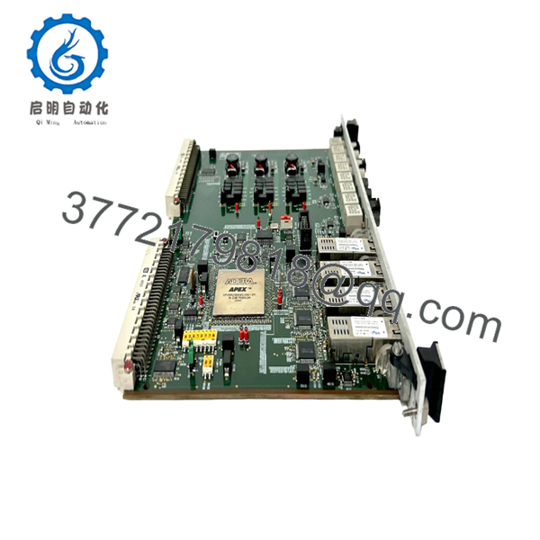
- Product Type: Power Interface Board / Industrial Control PCB
- Application: Industrial automation and control system interface
- Input Voltage: Verify exact rack configuration from OEM documentation before installation
- Communication Interface: Verify installed system protocol (site configuration dependent)
- Mounting Type: Control cabinet / rack-mounted module
- Operating Temperature: Verify OEM datasheet for installed system limits
- Firmware: Dependent on host control system configuration
- Compatibility: ALSTOM control system applications using PIB504 hardware reference
- Condition Available: New Original (New Surplus) or tested refurbished units depending on stock
4. Product Introduction
ALSTOM PIB504 is an industrial power interface board used in ALSTOM automation and control system architectures. The board provides interface functions between control electronics and connected system hardware in industrial applications where ALSTOM legacy platforms remain in operation.
In field replacements of legacy control hardware, engineers typically select PIB504 based on exact hardware revision, rack position, and existing configuration records. Verify the precise compatibility with OEM documentation before installation, especially for firmware-dependent systems.
5. Installation & Configuration Guide
Stage 1: Pre-Installation Preparation (Estimated Time: 5–10 minutes)
⚠️ Safety First:
- Notify plant operations before removing the module.
- Confirm the equipment is in a safe operating condition.
- Apply lockout/tagout procedures.
- Remove control power and wait at least 5 minutes for capacitor discharge.
Tools Required:
- ESD wrist strap
- PH1 screwdriver
- Fluke 115 multimeter
- Wire labels
- Smartphone/camera for documentation
Data Backup:
- Record the existing module position and rack location.
- Photograph all wiring, terminal positions, jumpers, and switch settings.
- Document cabinet identification and hardware revision markings.
- Save available controller configuration files before removal.
Stage 2: Removing the Old Module (Estimated Time: 5 minutes)
- Remove the front cover or protective bezel if installed.
- Label every connection before disconnecting.
- Disconnect wiring carefully. Do not pull terminals by force.
- Release rack locking tabs or mounting clips.
- Pull the module straight out to protect backplane pins.
- Inspect the backplane connector for bent pins, contamination, or mechanical damage.
⚠️ Note: Keep the original PIB504 installed until the replacement unit completes testing. The old board is often the best reference for jumper positions and revision comparison.
Stage 3: Installing the New Module (Estimated Time: 10 minutes)
- Wear an ESD strap and work on an ESD-safe surface.
- Verify the replacement marking matches the removed ALSTOM PIB504 module.
- Configuration Clone (Critical):
- Copy all jumper settings from the original board.
- Match hardware revision information.
- Confirm rack position and address settings where applicable.
- Insert the module into the rack until fully seated.
- Confirm locking tabs engage correctly.
- Reconnect wiring using appropriate tightening force.
Self-Checklist:
- Model number verified
- Board revision checked
- Jumpers/settings matched
- Wiring secured
- Rack locking mechanism engaged
Stage 4: Power-On & Testing (Estimated Time: 10–15 minutes)
Pre-Power Check:
- Use a Fluke 115 multimeter to verify the supply rail has no short condition.
- Confirm wiring polarity and grounding.
Power-On Steps:
- Energize the control rack only.
- Observe board status indicators if available.
- Check controller diagnostics for hardware recognition.
- Verify communication status with the connected control system.
- Run I/O or interface checks before returning equipment to production.
⚠️ Troubleshooting Note:
If the system does not recognize the board, check hardware revision compatibility first. Legacy ALSTOM systems can be sensitive to module revisions and configuration differences.

- PIB504
- PIB504
6. Frequently Asked Questions (FAQ)
Q: Can I hot-swap the ALSTOM PIB504 under power?
A: No, treat the PIB504 as a powered control board unless the exact system documentation confirms hot-swap capability. Removing a live board can damage the backplane or create unexpected controller faults. Always isolate power first.
Q: Is the ALSTOM PIB504 obsolete?
A: Many ALSTOM legacy automation modules have limited OEM availability because newer control platforms have replaced older architectures. Stock usually comes from New Original (New Surplus) inventory or tested refurbished sources. Verify hardware revision before ordering.
Q: Is this a genuine new ALSTOM PIB504 or refurbished?
A: Condition should be clearly identified before purchase. New Original / New Surplus units normally retain original factory markings and have not been installed. Refurbished units should include functional test records. Ask for serial verification and inspection photos if required.
Q: Will I lose my control program when replacing the PIB504?
A: The PIB504 is an interface board, not typically the location where the main application logic is stored. However, system behavior depends on the ALSTOM control architecture. Always document the existing configuration before removal.
Q: Why is this module available below OEM list pricing?
A: Industrial automation components often remain in service long after OEM production ends. Lower pricing usually comes from surplus inventory channels rather than new OEM production. Confirm condition, testing method, and warranty terms before purchase.
Q: What checks should I perform before installation?
A: Compare the complete model marking, hardware revision, connectors, and configuration settings. I have seen replacement projects delayed because a visually similar board had a different revision and the system rejected it after startup.
Q: What quality inspection should I expect before receiving a PIB504?
A: A proper inspection process should include:
- Inbound Inspection & Traceability
- Verify source records using OEM packing information or inventory documentation.
- Check serial numbers and identification markings.
- Inspect for corrosion, scratches, rework marks, or UV damage.
- Confirm available accessories and documentation.
- Live Functional Testing
- Test on a compatible industrial control rack or simulation environment.
- Verify power-up sequence and indicator status.
- Perform communication checks where applicable.
- Run functional testing under load conditions.
- Generate a test report.
- Electrical Testing
- Insulation resistance testing using a 500 V Megger where applicable.
- Ground continuity verification.
- Additional electrical checks based on board design.
- Configuration Verification
- Record hardware revision information.
- Document jumper settings and configuration details.
- Store photographic records.
- Final QC & Packaging
- QC inspector approval.
- Anti-static ESD packaging.
- Protective cushioning and heavy-duty boxing.
- QC label with inspection date.
Test photos and videos can be provided upon request. Verified functional testing under controlled conditions is the practical standard for legacy automation boards.



