WhatsApp: +86 16626708626
 Email:
 Phone: +86 16626708626
Description
Core Product Summary (Brand / Model / Key Attributes)
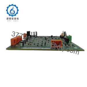
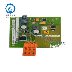
The Alstom V4550220-0100 is an industrial-grade electronic circuit card and system interface processing module designed for integration into Alstom’s ALSPA automation and distributed control system (DCS) architectures. Engineered for high-reliability process control in power generation plants, electrical substations, and heavy industrial facilities, the module performs real-time signal processing, system logic execution, and localized control-bus interfacing.
Identified by part number V4550220-0100, the module features a rugged rack-mountable printed circuit board (PCB) assembly equipped with high-density backplane connectors and front-panel diagnostic indicators. It operates within dedicated ALSPA controller chassis sub-racks, handling high-speed data exchanges between field input/output (I/O) modules and the central system processing units.
Key Technical Specifications
| Parameter | Specification |
| Part Number | V4550220-0100 |
| Manufacturer | Alstom |
| Product Family | ALSPA Series / Control System Architecture |
| Module Type | Interface Processing Module / Controller Circuit Card |
| System Mounting | Slide-in Sub-Rack / Chassis Backplane Mount |
| Front Diagnostics | LED Status Indicators (Power, Status, Bus Activity) |
| Cooling Method | Natural Convection / Rack Fan Tray |
| Operating Temperature | 0°C to 60°C (32°F to 140°F) |
Detailed Product Overview
The Alstom V4550220-0100 interface card serves as an embedded control component within Alstom’s legacy and specialized ALSPA control infrastructure. In power generation and industrial automation networks, system stability depends on low-latency, deterministic processing between field-level sensor networks and central supervisory controllers. The V4550220-0100 provides the necessary hardware layer to ensure reliable signal routing and system communication under continuous operation.
The physical assembly consists of an industrial-grade multi-layer printed circuit board designed to fit standard ALSPA system rack card guides. High-reliability gold-plated rear edge connectors mate directly with the internal rack backplane, establishing secure electrical connections for logic power, internal system bus data, and signal lines.
The module faceplate includes LED diagnostic indicators that display real-time operational status, system health, and communication traffic activity. Built-in hardware filtering and ground-isolation techniques protect onboard microelectronics against industrial noise spikes, electrical fast transients, and electromagnetic interference commonly encountered in power plant and substation environments.
Engineering Selection Highlights
- Native ALSPA Platform Fit → Purpose-built for Alstom ALSPA controller sub-racks, ensuring backplane timing compatibility, physical form-factor alignment, and system software recognition.
- High Noise Immunity → Integrated isolation and shielding design resist electromagnetic interference (EMI) and power system transients in harsh electrical environments.
- Real-Time LED Diagnostics → Faceplate LEDs provide immediate status verification for field engineers during system startup, routine maintenance, or fault troubleshooting.
- Sub-Rack Direct Insertion → Slide-in board format allows straightforward alignment into rack card guides, simplifying hardware upgrades and panel maintenance.
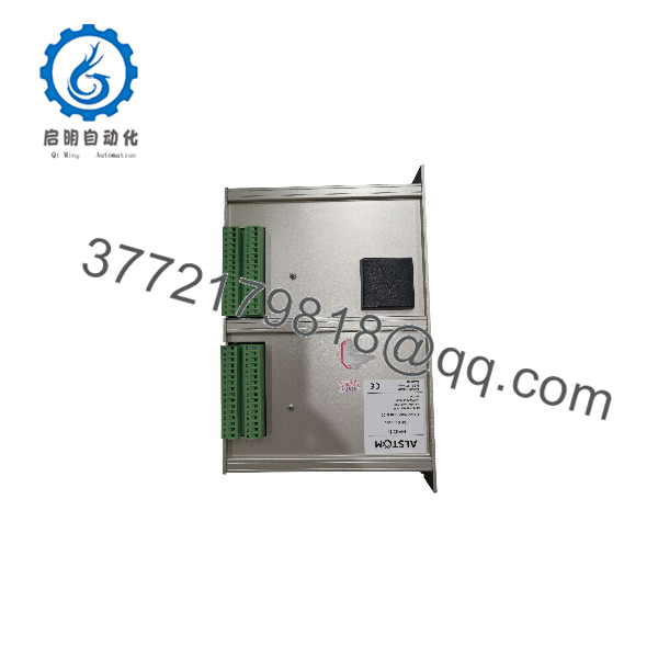
V4550220-0100
System Compatibility & Integration Requirements
| Item / Dependency | Verified Compatibility or Requirement | Practical Note |
| Host Chassis | Alstom ALSPA Controller Rack Assembly | Installs into dedicated system sub-rack slots designed for ALSPA series cards. |
| Backplane Interface | ALSPA Internal System Bus | Mates with backplane edge connectors for DC power and internal data communication. |
| Hardware Configuration | ALSPA Engineering Software / DIP Switches | Address setting or parameter recognition must be configured per plant engineering documentation. |
Dimensions, Mounting & Connection Notes
- Form Factor: Standard plug-in Eurocard-style printed circuit board for Alstom controller racks.
- Mounting: Vertical card-guide insertion into designated sub-rack slots; front faceplate thumbscrews secure the module against vibration.
- Backplane Connections: High-density rear edge connector plugs into the rack backplane for power and signal routing.
- ESD Handling: Static-sensitive device. Operators must wear a grounded anti-static wrist strap and handle the card strictly by its metal faceplate or edge pullers.
FAQ
What is the Alstom V4550220-0100?
The Alstom V4550220-0100 is a dedicated circuit board interface processing module designed for use within Alstom ALSPA control and automation system racks.
What applications typically use the V4550220-0100 module?
It is primarily utilized in power generation, substation control, and large-scale process automation systems built around Alstom ALSPA distributed control platforms.
How is the V4550220-0100 installed in the system?
The board slides into a designated slot within an ALSPA system rack, engaging the backplane connector, and is secured at the faceplate using mounting screws.
Does the module feature visual diagnostic indicators?
Yes, the front panel includes status LEDs that indicate module power, operational health, and communication activity.
Verification & Troubleshooting Notes
High Voltage & ESD Safety Notice
Always de-energize main AC/DC supply power to the controller rack assembly before inserting or removing the V4550220-0100 module. Always wear a grounded anti-static wrist strap when handling circuit cards to prevent electrostatic discharge damage to internal components.
1.Verify Board Seating and Mounting:Physical check.
Ensure the V4550220-0100 card is pushed fully into the rack card guides until the rear connector seats firmly into the backplane. Tighten top and bottom faceplate screws.
Verification: The card sits flush with adjacent modules in the rack, and the green POWER LED illuminates steadily upon applying rack power.
2.Inspect Status LEDs for System Faults:Diagnostic check.
Observe the LED status pattern on the module faceplate following power-up initialization.
Verification: Status indicators display normal operational status (typically steady green/blinking activity) without persistent FAULT or ERROR illumination.
3.Verify Node Detection in DCS Workstation:System check.
Access the ALSPA engineering software workstation to scan the local rack sub-system.
Verification: The workstation software identifies the V4550220-0100 card at its assigned rack/slot address without reporting hardware mismatch errors.