
 WhatsApp: +86 16626708626
 Email:
  Phone: +86 16626708626
Description
Key Technical Specifications
| Parameter | Value |
|---|---|
| Manufacturer | Applied Materials, Inc. |
| Part Number | 0090-76110 |
| Product Identification | Synergy V21 VME CPU / single-board computer |
| Product Type | VMEbus CPU board / SBC controller PCB |
| Primary Application | Control hardware for Applied Materials semiconductor manufacturing equipment |
| System Architecture | Applied Materials Synergy electronics platform |
| Host Backplane | VMEbus chassis/backplane |
| Board Format | 6U VME form factor reported by market sources; verify actual board depth and front-panel configuration |
| Board Revision | Rev A appears in market listings; confirm the exact physical revision label |
| Processor Details | Not reliably verified from OEM documentation; do not publish processor, clock speed, or memory claims without board-label evidence |
| Operating System / Firmware | Tool-specific AMAT firmware and configuration; must match the installed tool software and hardware architecture |
| I/O Interface | VME backplane interface plus tool-specific front-panel connections; verify connector layout from the installed board |
| Compatibility | Requires exact Synergy V21 tool, chassis, software, and revision validation |
| Lifecycle Status | Legacy semiconductor-tool spare; source availability is typically New Surplus, used, or refurbished stock |
Available listings consistently identify the AMAT 0090-76110 as a Synergy V21 VME CPU or VME single-board computer for Applied Materials equipment. Several web pages claim unrelated processor, memory, or application details, including claims that it is a generic VME PCB, bus board, PECVD reactor, or field-control processor. Those claims conflict and are not sufficient for a technical specification. Verify the physical board label, revision, tool bill of materials, and AMAT service documentation before ordering.
Product Introduction
The Applied Materials 0090-76110 is a Synergy V21 VME CPU board used in legacy Applied Materials semiconductor equipment. Installed in a VME chassis, it provides processor-level control for tool sequences, interlocks, communications, process interfaces, and other machine-control functions defined by the specific AMAT system configuration.
This is not a universal VME controller. A board can physically fit the VME backplane and still fail to boot the tool if its firmware, board revision, front-panel interfaces, option configuration, or software version differs from the installed Synergy system. Confirm the exact 0090-76110 label, revision, tool model, chassis slot, and available backup media before replacing it.
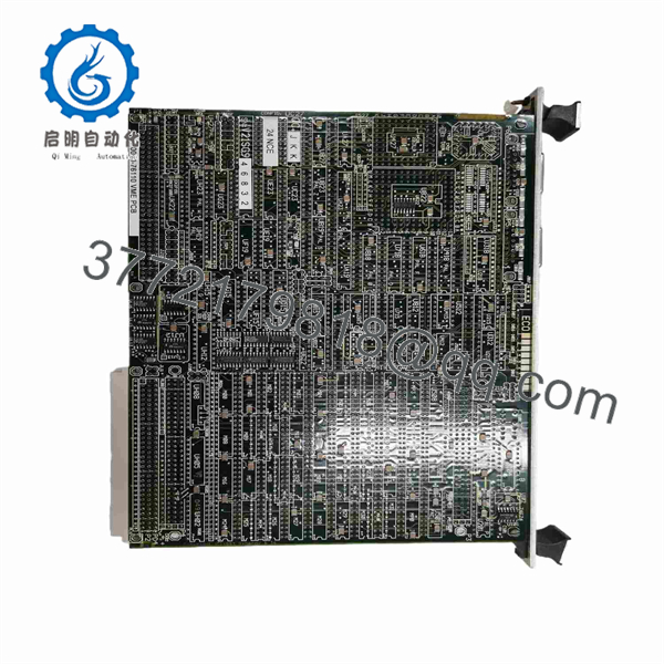
0090-76110
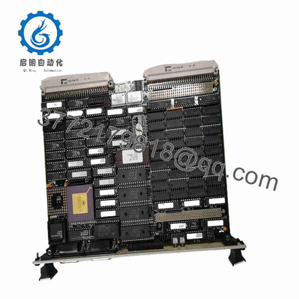
0090-76110
Troubleshooting Quick Reference
| Symptom | Possible Cause | Relevance to This Part | Quick Check Method | Recommendation |
|---|---|---|---|---|
| Tool controller does not boot | VME chassis supply fault, loose CPU board, failed 0090-76110, corrupted boot media, backplane fault | ⚠️ Medium | Measure chassis power rails according to the VME rack service documentation; power down and inspect the board-edge connector and card guides | Verify rack power and backplane condition before replacing the CPU board |
| CPU board has no front-panel indicators | Missing VME supply voltage, board not seated, failed chassis supply, failed board | ⚠️ Medium | Check VME supply rails at the chassis test points and inspect the module seating; compare LED behavior with a known-good board if available | Start with chassis power. A dead board indication is not enough to prove board failure |
| Tool freezes during boot or hangs at initialization | Corrupt firmware, mismatched board revision, failed RAM/CPU section, VME bus contention, peripheral board fault | ✅ High | Record the exact boot message or diagnostic code; remove or isolate nonessential tool boards only under approved OEM procedures | Compare board revision and firmware with the original before installing a replacement |
| Replacement board powers up but tool configuration is missing | Wrong firmware image, missing tool-specific configuration, incorrect board revision, nonvolatile-memory issue | ✅ High | Compare all labels, firmware stickers, configuration jumpers, and backup media with the removed unit | Do not run process hardware until the correct tool configuration is restored and verified |
| Tool reports VME bus communication errors | Loose card edge, damaged backplane connector, failed peripheral board, CPU VME interface fault | ⚠️ Medium | With power isolated, inspect VME slot connectors and card edges for bent contacts, corrosion, or heat marks; check whether the error follows the board or stays with the slot | Determine whether the fault follows the CPU, another VME card, or the chassis before replacement |
| Intermittent faults occur after cabinet warm-up | Aging components, poor cooling, marginal VME supply, cracked solder joint, backplane contact issue | ✅ High | Trend chassis temperature and supply rails; test the board in a known-good compatible chassis if plant procedures permit | Correct cooling and power issues first. A thermal fault that follows the board supports replacement or repair |
| Controller communicates with some subsystems but not others | Peripheral I/O board fault, cable fault, field-device issue, software configuration error | ❌ Low | Review tool diagnostics and isolate affected interfaces; verify downstream boards and cables before replacing the CPU board | Do not replace the CPU for a localized peripheral failure |
| New board causes different tool alarms | Firmware, revision, configuration, or option mismatch | ✅ High | Compare every alarm against the old board’s final diagnostic records; verify board revision, ROM labels, and tool software compatibility | Stop commissioning and obtain the correct matching board or OEM-approved firmware |
| Board will not seat correctly | Wrong VME format, wrong board depth, damaged ejector, incorrect card guide, connector mismatch | ✅ High | Compare front panel, ejectors, board dimensions, connector keying, and card-edge layout against the removed unit | Do not force insertion. Mechanical damage to a VME backplane is expensive and can disable the entire tool |
| Tool failure remains after CPU replacement | Problem lies in chassis power, backplane, software, boot storage, or external interface board | ❌ Low | Reinstall the old board if safe and compare behavior; review fault history and supply measurements | Continue systematic diagnosis. Do not assume the replacement board is defective without evidence |
❗ Before removing the original board, make a full recovery record: photographs of the faceplate, board labels, revision labels, firmware/ROM stickers, jumpers, DIP switches, VME slot, adjacent modules, and all boot errors. Capture available tool software, configuration files, parameter backups, and service logs. That record is the difference between a controlled board replacement and a semiconductor-tool recovery event.
Do not move jumpers or ROMs from memory. I have seen VME systems stay down for days because a replacement CPU board had a different boot configuration even though the part number looked correct.
If the diagnosis is uncertain, provide technical support with tool model and software revision, photos of both boards, VME slot location, boot screen or alarm history, chassis supply measurements, and a copy of the system configuration backup.
Frequently Asked Questions
What is the Applied Materials 0090-76110?
The Applied Materials 0090-76110 is identified as a Synergy V21 VME CPU board or VME single-board computer used in Applied Materials semiconductor-equipment control architecture. It installs in a VME chassis and provides tool-specific processor/control functions.
Is 0090-76110 a generic VME CPU board?
No. Although it uses the VMEbus format, it is an AMAT tool-specific spare. The VME mechanical standard does not guarantee firmware, software, backplane, front-panel I/O, or process-tool compatibility. An unrelated VME CPU board may fit the chassis but will not operate an Applied Materials Synergy system.
Is it the same as AMAT 0090-76111?
Do not assume so. AMAT part-number sequences often include revision, assembly, daughterboard, or configuration differences that are not visible from the base description. One secondary listing references 0090-76111 as a separate Synergy V21 assembly, which is enough reason to treat it as a separate part until AMAT documentation confirms interchangeability. Match the exact 0090-76110 number and board revision.
Can I hot-swap this VME CPU board?
No. Treat this legacy VME CPU board as non-hot-swappable. Shut down the equipment according to the tool’s approved procedure, isolate electrical energy, observe lockout/tagout requirements, wait for stored energy to discharge where applicable, and verify the system is safe before handling the board. Hot removal can corrupt VME bus operation, damage the backplane, or leave process equipment in an uncontrolled state.
Will I lose the tool configuration when replacing the board?
Possibly. Tool configuration may be stored in nonvolatile memory on the CPU board, on boot media, on another controller, or in the equipment software environment. Do not assume the replacement contains the correct firmware or configuration. Back up all accessible system software, recipes, parameters, calibration records, network settings, and service files before removal.
Why does a replacement board boot but still show tool faults?
A successful boot only proves that part of the CPU system is alive. The tool can still fault due to incompatible firmware, wrong board revision, missing configuration, a bad VME peripheral card, backplane damage, missing I/O communications, or process-system interlocks. Compare fault logs and hardware inventory against the original operating configuration before changing more hardware.
Is the 0090-76110 obsolete, and should I stock a spare?
Treat it as a legacy semiconductor-equipment spare. Current availability is generally through New Surplus, used, refurbished, or repair-channel inventory, and exact revision matching can be limited. If the tool is production-critical, keep a verified spare, the full system recovery media, a VME chassis inventory, photographs of board positions, and written replacement procedures.
What testing should a supplier perform before shipment?
For New Original / New Surplus stock, request actual photos of the front panel, full part number, revision label, ROM/firmware labels, card edge, and any jumpers or DIP switches. The supplier should inspect for corrosion, damaged traces, rework marks, heat discoloration, bent connector contacts, and damaged ejector hardware. Require ESD-safe packaging and rigid protection around the VME board edge.
For Refurbished stock, request testing in a compatible VME chassis. The report should document correct chassis power-up, CPU boot sequence, VMEbus enumeration or communication, front-panel status behavior, memory or self-test results where supported, communication with representative VME I/O hardware, a controlled thermal run, and final QC sign-off. Request the test report, actual-unit photographs, written condition statement, warranty terms, and confirmation of firmware/revision details before shipment.



