
 WhatsApp: +86 16626708626
 Email:
  Phone: +86 16626708626
Description
Key Technical Specifications
| Parameter | Value |
|---|---|
| Manufacturer / Equipment OEM | Applied Materials, Inc. |
| Part Number | 0100-00003 |
| Common Product Description | Stepper Drive / Stepper Drive Controller |
| Product Type | VME motion-control PCB / stepper-drive board |
| Bus Architecture | VMEbus |
| Form Factor | B-size VME module |
| Primary Function | Drives and controls stepper-motor motion in AMAT semiconductor equipment |
| Reported Tool Association | Applied Materials P5000; verify against the actual tool bill of materials |
| Known Board Revisions | Rev. B and Rev. C reported in market and repair records |
| Original Board Manufacturer Association | RadiSys is identified in VME stepper-drive listings; confirm physical OEM labeling |
| Host Installation | Compatible VME chassis/backplane in the applicable Applied Materials tool |
| Motor Interface | Tool-specific stepper motor and cable interface; verify connector pinout and motor requirements |
| Firmware / Configuration | Tool-specific; confirm revision, jumpers, configuration records, and host software compatibility |
| Weight Reference | Approximately 0.4 kg / 0.88 lb in one pre-owned listing; verify actual shipping weight |
| Lifecycle Status | Obsolete / legacy semiconductor-tool spare |
Available technical marketplace and repair records consistently identify the AMAT 0100-00003 as a B-size VME stepper-drive board, with Rev. B and Rev. C variants, used in legacy Applied Materials motion-control applications. Listings associate it with P5000 equipment and identify RadiSys as the underlying VME board supplier in some channels. Exact output current, motor voltage, microstepping configuration, connector pinout, and firmware details were not verified from an OEM datasheet; do not infer them from generic VME or stepper-drive products.
Product Introduction
The Applied Materials 0100-00003 is a VMEbus stepper-drive controller board used in legacy semiconductor manufacturing equipment. It provides the controlled motion interface for one or more stepper-driven mechanical functions within the machine, where repeatable positioning, controlled acceleration, and coordinated tool sequencing are required. Market records specifically associate the board with Applied Materials P5000 stepper-controller applications.
This is a system-specific VME motion board, not a generic standalone stepper driver. A replacement must match the physical board revision, VME chassis, tool software, motor wiring, encoder or limit-switch interfaces where used, and motion configuration. Confirm the exact part number, revision, front-panel layout, connector set, and installed board location before ordering.
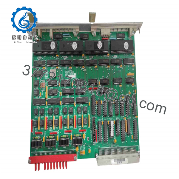
0100-00003
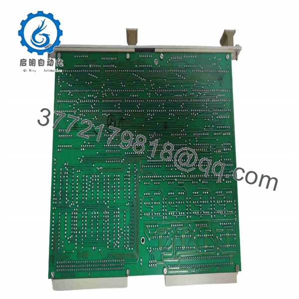
0100-00003
Troubleshooting Quick Reference
| Symptom | Possible Cause | Relevance to This Part | Quick Check Method | Recommendation |
|---|---|---|---|---|
| Stepper axis does not move | Motion inhibit active, missing motor supply, failed cable, mechanical jam, failed drive board, host command issue | ⚠️ Medium | Check tool diagnostics and motion interlocks; measure required motor-power supply at the system terminals per the AMAT schematic | Verify interlocks, power, and mechanics before replacing the board |
| Board has no power or front-panel activity | VME rack power fault, board not seated, blown fuse, failed VME backplane, failed board | ⚠️ Medium | Measure VME chassis supply rails at approved test points; power down and inspect board-edge contacts and slot guides | Check rack power and seating first. Do not assume a dead board is the root cause |
| Stepper motor hums but does not rotate | Mechanical binding, motor phase open, cable fault, missing drive phase, incorrect current setting, failed output stage | ✅ High | Isolate the system safely, inspect motor cable and connector; check motor phase resistance and compare phase-to-phase balance | Remove the mechanical load if permitted. If the motor and cable are sound, evaluate the drive board |
| Axis moves but loses position | Mechanical slip, coupler damage, missed steps, overload, ramp too aggressive, cable intermittency | ⚠️ Medium | Inspect coupling, belts, lead screw, and hard stops; compare commanded motion with known reference or limit feedback | Correct mechanical load and acceleration profile before replacing the board |
| Axis faults only during fast moves | Acceleration too high, supply-voltage sag, motor torque limit, cable issue, failing output stage | ⚠️ Medium | Reduce acceleration under approved maintenance conditions; measure supply voltage during movement and review fault log | Verify load and power supply first. A good board can fault on an overloaded axis |
| One direction works but the reverse direction fails | Broken control signal, limit switch active, wiring issue, output-stage fault, host logic configuration | ✅ High | Check directional command and limit-switch status in diagnostics; inspect cable continuity and limit inputs | Verify limits and control signals before declaring a board failure |
| Motor runs hot at standstill | Excessive holding current, incorrect configuration, stalled mechanics, failing driver output stage | ⚠️ Medium | Check motor current with a suitable meter and monitor motor-case temperature; verify that the axis is not forced against a hard stop | Stop operation if overheating occurs. Review configuration and mechanics before replacement |
| Tool reports VME bus fault | Loose board edge, damaged VME slot, chassis supply issue, another VME board fault, failed CPU interface | ⚠️ Medium | With power isolated, inspect VME connector contacts and test the board in a known-good slot only if OEM procedure permits | Determine whether the error follows the board or remains with the chassis slot |
| New board boots but motion is incorrect | Wrong revision, jumpers/configuration mismatch, incompatible firmware, connector mismatch, incorrect host configuration | ✅ High | Compare all labels, revisions, jumpers, DIP switches, cable positions, and configuration records against the old board | Do not change settings from memory. Restore the known machine configuration before testing |
| Replacement board does not physically fit | Wrong VME form factor, incorrect ejector position, different front panel, connector variation, damaged card guides | ✅ High | Compare the old and replacement board front panel, card-edge profile, board dimensions, connector arrangement, and revision labels | Do not force the board into the chassis. Return it if any mechanical or connector detail differs |
❗ A stepper motor can hum and still be electrically healthy. That symptom often comes from a jammed mechanism, open motor phase, failed cable, or missing drive phase. Do not replace the AMAT 0100-00003 until you have checked the motor phase resistance, cable continuity, mechanical travel, and the required power supply.
Before removal, photograph the entire board, both labels, front panel, VME slot, card-edge, jumpers, DIP switches, motor connectors, cable labels, and adjacent VME boards. Record the exact tool alarm, axis name, motion sequence, and whether the fault occurs in one direction or both. That record prevents an incorrect Rev. B/Rev. C or configuration swap.
If the fault remains unclear, provide technical support with the tool model, board revision, VME chassis slot, motor part number, motor phase-resistance readings, fault log, supply-voltage measurements, and close photographs of all connectors.
Frequently Asked Questions
What is the Applied Materials 0100-00003?
The Applied Materials 0100-00003 is a legacy VME stepper-drive controller board used for stepper-motor motion control in Applied Materials semiconductor equipment. Available listings identify it as a B-size VME module and associate it with P5000 motion-control applications.
Is the 0100-00003 a standalone stepper driver?
No. It is a VMEbus circuit board designed to operate inside the specific VME chassis and machine-control architecture used by the applicable AMAT tool. It needs the host CPU, backplane, correct power supplies, machine wiring, interlocks, and tool software. Do not attempt to operate it as an external bench-top driver without the proper system documentation and test fixture.
Are Rev. B and Rev. C interchangeable?
Do not assume they are. Repair and market records show Rev. B and Rev. C boards, but a revision can change component placement, firmware, jumper settings, connector behavior, or host-software requirements. Match the full part number and exact revision label unless the equipment documentation or AMAT engineering support confirms substitution.
Is this board made by Applied Materials or RadiSys?
Applied Materials uses the board as an equipment spare, while some listings identify RadiSys as the VME board supplier. That relationship does not establish that every RadiSys-branded unit is interchangeable with an AMAT-labeled 0100-00003. Match AMAT labels, revision, front-panel configuration, and tool documentation.
Can I hot-swap the 0100-00003?
No. Shut down the tool according to approved semiconductor-equipment procedures, isolate electrical energy, observe lockout/tagout requirements, and verify the VME chassis is de-energized before removing the board. Hot removal can interrupt motion control, damage the VME backplane, corrupt system operation, or cause uncontrolled machine behavior.
Why does the motor still not move after replacing the board?
The root cause may be outside the board: motion interlocks, door switches, pneumatic or vacuum permissives, limit switches, motor power supply, motor cable, motor winding, a jammed lead screw, a failed coupling, or host software. Use tool diagnostics and physical measurements to isolate the fault. Do not replace a second motion board until you have proven the motor and mechanical axis are sound.
Is the 0100-00003 obsolete, and should I keep a spare?
Yes. Treat it as an obsolete semiconductor-tool motion spare. Current supply is generally New Surplus, used, refurbished, repair-channel inventory, or board-level repair. For production-critical equipment, keep an exact verified spare with the required revision, retain system backups, document VME board locations, and keep photographs of connectors and settings.
What testing should a supplier perform before shipment?
For New Original / New Surplus stock, request actual photos of the full board, AMAT label, revision label, front panel, card edge, connectors, jumpers, and DIP switches. The supplier should inspect for corrosion, bent contacts, damaged traces, heat discoloration, rework evidence, and damaged ejector hardware. Require ESD-safe packaging and rigid support around the VME card edge.
For Refurbished stock, request functional testing in a compatible VME environment with an equivalent stepper-motor load or qualified simulator. The test report should document VME power-up, board recognition, axis-enable behavior, directional command response, controlled stepping, output stability, fault detection, connector continuity, thermal operation, and final QC sign-off. Ask for test photos or video, actual-unit photographs, written condition status, warranty terms, and confirmation that the tested board matches the ordered revision.



