
 WhatsApp: +86 16626708626
 Email:
  Phone: +86 16626708626
Description
Key Technical Specifications
- Manufacturer: Applied Materials, Inc. (AMAT)
- Part Number: 0100-71267
- Revision Identified in Listings: Rev. 01
- Associated Fabrication Drawing: 0110-71267
- Card Description: 8-Channel PMC/PCM Card
- Channel Count: 8
- Form Factor: Printed circuit board / mezzanine-style control card; verify the installed host platform before ordering
- Primary Application: Semiconductor manufacturing equipment control and subsystem interfacing
- Country of Manufacture Identified in Listing: United States
- Replacement Requirement: Match AMAT part number, revision, connector arrangement, and installed-system configuration
- Firmware/Configuration: Not publicly verified; document the installed card’s labels, jumpers, and host-controller configuration before replacement
- Electrical Ratings: Input voltage, I/O signal type, channel function, and backplane/interface pinout require confirmation from the AMAT equipment documentation or the removed card label
The available market listings consistently identify 0100-71267 as an Applied Materials 8-channel PMC/PCM card and associate it with fabrication drawing 0110-71267. Public listings conflict on the expanded acronym and application description, so do not assume it is a generic counter, remote I/O, or VME motion-control card without matching the physical assembly and AMAT documentation.
Product Introduction
The Applied Materials 0100-71267 is an 8-channel PMC/PCM control-card assembly used in AMAT semiconductor-processing equipment. It provides a dedicated multi-channel interface function within the original equipment control architecture and should be replaced only by the exact 0100-71267 assembly or an OEM-approved substitute.
Buyers select this part when an installed semiconductor tool requires an exact physical and electrical replacement rather than a generic industrial I/O card. Confirm Rev. 01, FAB DWG 0110-71267, connector layout, installed host board, and site configuration before releasing a purchase order.
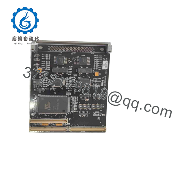
0100-71267
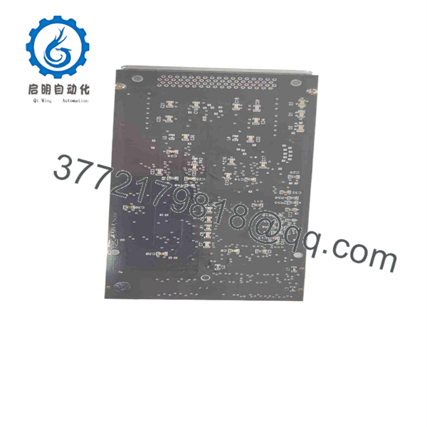
0100-71267
Troubleshooting Quick Reference
| Symptom | Possible Cause | Relevance to This Part | Quick Check Method | Recommendation |
|---|---|---|---|---|
| No machine response from all eight connected channels | Card not powered, host controller fault, connector partially seated, or card failure | ✅ High | Apply equipment lockout/tagout. Verify the host system reaches normal boot status. Inspect card seating and connector engagement. Measure the documented supply rails at the card interface using a Fluke 115 or equivalent meter. | Check system power and host-controller health before replacing the card. Replace only after confirming correct supply rails and secure seating. |
| One channel does not respond but the other seven work | Field wiring defect, failed sensor/actuator, connector pin damage, or one failed channel | ✅ Medium | Swap the field cable or known-good load with a working channel if the equipment procedure permits. Inspect connector pins under magnification. Compare measured field signals at the source and card connector. | Do not condemn the full card immediately. Isolate the field device, cable, and connector first. |
| Several channels show intermittent faults | Loose cable, contaminated connector, vibration, grounding issue, or marginal card solder joint | ✅ Medium | With power removed, inspect connectors for bent pins, oxidation, residue, and inadequate strain relief. Review fault history for correlation with motion, temperature, or maintenance work. | Reseat connectors and correct wiring or grounding defects. If the symptom follows the card after controlled substitution, replace the card. |
| Host controller reports communication timeout after replacement | Revision mismatch, incorrect card identification, incorrect slot, or configuration mismatch | ✅ High | Photograph the original card label, revision marking, connector positions, jumpers, and slot location before removal. Compare every marking with the replacement. Review equipment diagnostics and configuration records. | Verify AMAT part number 0100-71267 and revision compatibility. Do not install an assumed equivalent card based solely on appearance. |
| Tool faults immediately after card installation | Bent connector pin, incorrect orientation, ESD damage, displaced adjacent board, or incompatible replacement | ✅ High | Power down immediately. Inspect the mating connector and backplane. Confirm the card is fully aligned and that no pins were pushed back. Check for unusual heating or odor; do not continue energizing a suspect installation. | Remove the card and inspect the installation. Use ESD controls and verify every connector before the next power-up. |
| Machine alarm points to an external sensor or actuator | Field device, power supply, fuse, wiring, interposing relay, or external subsystem issue | ❌ Low to Medium | Measure the signal at the field device and again at the card-side connector. Check the applicable fuse, terminal block, cable shield termination, and 24 V DC control supply where applicable. | Correct the external problem first. Semiconductor equipment cards are often blamed when the actual fault is a damaged cable or failed field device. |
| No visible damage, but repeated unexplained process faults occur | Intermittent electronic failure, thermal stress, oxidation, or configuration corruption | ✅ Medium | Review diagnostic logs and capture photographs of card labels and LEDs before removal. If approved by site procedures, perform a controlled swap with a verified matching spare. | Keep the original card for comparison. Provide fault logs, equipment model, photos, and installed-card labels to technical support before ordering. |
❗ Field warning: Take clear photographs of every connector, slot location, jumper, and label before touching the installed card. This is the most common way technicians avoid a two-day recovery effort caused by a correct part installed with one cable or configuration detail wrong.
❗ ESD warning: Wear a grounded wrist strap and store the board in a shielding bag. I have seen expensive controller cards fail on first power-up after being handled bare-handed in dry conditions. It is a preventable mistake.
If the fault remains unclear, contact technical support with high-resolution photos of both sides of the installed assembly, the AMAT tool model, the exact alarm text, diagnostic logs, and the part/revision labels. Keep these checks in mind and you will save yourself 90% of typical rework time.
Frequently Asked Questions (FAQ)
Is AMAT 0100-71267 a generic industrial I/O module?
No. Available listings identify it as an Applied Materials 8-channel PMC/PCM card intended for semiconductor equipment, not as a standard PLC rack I/O module. Although some reseller descriptions assign different generic functions to the same number, those descriptions should not be treated as OEM confirmation. Match the AMAT part number, revision, physical layout, connectors, and tool documentation before purchase.
Can I replace 0100-71267 with another eight-channel card?
No, not safely based on channel count alone. “Eight-channel” does not establish electrical compatibility, signal type, connector pinout, host interface, firmware behavior, or AMAT tool configuration. A physically similar card can still damage a mating interface or leave the machine unable to initialize. Purchase an exact 0100-71267 replacement unless Applied Materials provides a documented supersession.
Is this card hot-swappable?
Assume no unless the exact AMAT equipment manual explicitly authorizes hot replacement for this assembly. Powering down may be necessary to protect the host controller, connector, and adjacent electronics. Kill power through the approved machine procedure, discharge stored energy where required, use ESD protection, and document cable placement before removal.
What should I document before removing the existing card?
Record the complete part number, revision, serial number, fabrication-drawing marking, all connector positions, slot location, cable labels, switch or jumper settings, and fault codes. Photograph both sides of the board before removal. If the original board still communicates, save the relevant machine diagnostics and configuration information first.
The mistake that causes the most downtime is not ordering the wrong number—it is installing the right number with one connector in the wrong location or with unrecorded jumper settings.
Does replacing the card erase machine programming or configuration?
The card may not hold the main machine program, but it can still affect address mapping, channel behavior, identification, calibration, or host-system startup. Public sources do not verify the memory or configuration architecture of 0100-71267. Back up the AMAT system configuration and capture the existing settings before pulling the original card. Do not assume a swap is plug-and-play.
Why is a New Surplus unit less expensive than buying from the OEM?
New Surplus normally means unused original inventory obtained through excess stock, canceled projects, distributor liquidation, or equipment decommissioning rather than the current OEM supply chain. It may arrive in original packaging, but packaging condition, label verification, accessory inclusion, storage history, and revision must be confirmed unit by unit.
For a surplus purchase, request actual photos of the card labels and connectors, confirmation of the revision, ESD-safe packaging details, functional-test evidence, stock quantity, ship date, and written warranty terms before payment.
How should a supplier test an AMAT 0100-71267 card before shipment?
A credible test process starts with inbound traceability and anti-counterfeit inspection: review OEM packing-list or customs documentation when available, verify serial or label markings, inspect for corrosion, scratches, rework marks, UV yellowing, damaged connectors, and missing hardware.
The supplier should then use the correct AMAT-compatible host fixture or a validated simulation setup—not merely a power supply—to check power-up behavior, interface communication, and all available channels. They should document the test duration, thermal observations, firmware or identification data where readable, and final inspection. Final packing should use an ESD shielding bag, protective cushioning, and a rigid corrugated carton. Ask for the actual test report, photos, and video before shipment; vague statements such as “tested OK” are not enough for a production spare.



