
 WhatsApp: +86 16626708626
 Email:
  Phone: +86 16626708626
Description
Key Technical Specifications
- Manufacturer: AMAT / Applied Materials
- Part Number: 0100-71271
- Revision Identified: Rev 03
- Product Category: PMC Card / Digital I/O Board
- Channel Count: 16 channels
- Bus/System: VMEbus-based equipment
- Board Function: Digital I/O interface
- Application: Semiconductor manufacturing equipment
- Board Type: Electronic circuit board assembly
- Country of Origin: Reported as USA by one commercial listing
- Dimensions: 135 × 186 × 119 mm reported by one reseller; verify against the physical board before installation
- Weight: 1.2 kg reported by one reseller; verify before shipping or mechanical integration
- Operating Voltage: Not reliably established from the available sources
- I/O Voltage Levels: Not reliably established from the available sources
- Connector Pinout: Not established from the available sources
- Firmware: Not established; verify the installed board revision and equipment configuration
Technical verification note: Public sources contain inconsistent descriptions of this part number. The strongest part-number evidence identifies 0100-71271 Rev 03 as a 16-channel PMC card PCB, while other commercial listings describe it more generally as a VMEbus digital I/O module. Do not infer input/output voltage, connector pinout, isolation arrangement, or electrical ratings from the part number alone.
Product Introduction
The AMAT 0100-71271 is an electronic control-board assembly associated with Applied Materials semiconductor manufacturing equipment. Available trade records specifically identify 0100-71271 Rev 03 as a 16-channel PMC card PCB, while industrial automation listings classify the part as a VMEbus digital I/O module.
For replacement work, the exact board revision, connector arrangement, equipment configuration, and installed software should be checked against the removed assembly. Public documentation for the electrical channel characteristics is limited, so application-specific verification is required before installation.
Installation & Configuration Guide
Stage 1: Pre-Installation Preparation — Approximately 10 Minutes
⚠️ Safety First: Put the semiconductor equipment into its approved maintenance state. Follow the equipment manufacturer’s shutdown procedure and applicable lockout/tagout requirements before accessing the control electronics.
Tools Required:
- ESD wrist strap and grounded ESD workstation
- Appropriate Phillips/flat-head screwdrivers
- Digital multimeter
- Connector labels
- Camera or smartphone for configuration photographs
- Equipment-specific service documentation
Data Backup:
- Record the equipment model and controller configuration.
- Photograph the existing 0100-71271 installation from several angles.
- Record the board revision and all visible identification labels.
- Photograph every connector before removal.
- Record cable routing and connector orientation.
- Save the current equipment configuration according to the OEM maintenance procedure.
⚠️ Do not assume that two boards with the same base part number are electrically interchangeable if their revisions or assembly configurations differ.
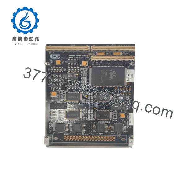
0100-71271
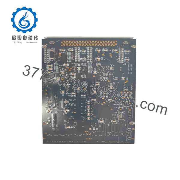
0100-71271
Stage 2: Removing the Old Module — Approximately 5 Minutes
- Confirm that the equipment has reached the required safe maintenance state.
- Apply ESD protection before touching the PCB.
- Remove the appropriate enclosure or card-cage access panel.
- Label each cable and connector before disconnection.
- Do not pull on individual wires or cable bundles.
- Release the board retaining hardware according to the equipment design.
- Pull the board straight from its mating connector or card-cage position.
- Inspect the mating connector for bent contacts, contamination, oxidation, or mechanical damage.
- Keep the removed board available for direct comparison until commissioning is complete.
⚠️ Do not use the board outline alone to determine connector orientation. Match the replacement against the original board and the equipment documentation.
Stage 3: Installing the New Module — Approximately 5 Minutes
- Verify that the replacement label reads AMAT 0100-71271.
- Confirm the board revision against the removed assembly.
- Compare connector locations, mounting holes, board markings, and visible component layout.
- Put on a grounded ESD wrist strap before handling the board.
- Do not touch exposed PCB contacts or connector pins unnecessarily.
- Insert the board squarely into its designated position.
- Apply only the manufacturer’s specified mechanical retention.
- Reconnect every cable according to the photographs and wiring documentation.
- Check that each connector is fully seated.
- Inspect for trapped cables, loose hardware, or foreign objects.
Replacement Checklist:
- Part number verified
- Board revision verified
- Connector locations matched
- Cable labels checked
- Board fully seated
- Retaining hardware secured
- ESD precautions maintained
Stage 4: Power-On & Testing — Approximately 10 Minutes
- Perform a final visual inspection before energizing the equipment.
- Verify that no loose metal objects or tools remain inside the enclosure.
- Restore power using the approved equipment startup sequence.
- Observe board and system diagnostic indicators.
- Check the equipment controller for hardware recognition.
- Verify the expected I/O status through the machine’s diagnostic interface.
- Exercise the applicable digital inputs and outputs using the OEM-approved test procedure.
- Check the equipment event log for communication, I/O, or configuration faults.
- Compare the replacement board’s reported identity/revision with the expected configuration.
- Return the equipment to production only after the required interlocks and process checks have passed.
⚠️ Troubleshooting Note: If the controller does not recognize the replacement, do not immediately assume the board is defective. First check board revision, connector seating, card position, configuration data, power rails, and the equipment-specific hardware compatibility requirements.
Frequently Asked Questions (FAQ)
Can the AMAT 0100-71271 be hot-swapped?
Do not assume that it is hot-swappable. The available public information does not establish a hot-swap capability for this specific assembly. Follow the Applied Materials equipment service procedure and remove power or place the equipment in the prescribed maintenance state before replacing the board.
Is 0100-71271 a VMEbus board?
Available commercial sources classify 0100-71271 as an AMAT VMEbus digital I/O module. Trade records also identify 0100-71271 Rev 03 as a 16-channel PMC card PCB. These descriptions should be treated as complementary identification information rather than a substitute for the equipment-specific manual.
Is this a 16-channel board?
Yes, available trade records specifically describe 0100-71271 Rev 03 as an assembled 16-channel PMC card PCB.
Does replacing 0100-71271 erase the equipment’s software or process recipe?
The board itself should not be assumed to contain the complete equipment application configuration. Whether configuration data is stored locally, in a controller, or elsewhere depends on the specific Applied Materials equipment architecture. Back up the equipment configuration before replacement and follow the OEM recovery procedure.
What should I verify before ordering a replacement?
At minimum, provide the supplier with the complete 0100-71271 part number, visible revision, equipment model/platform, and photographs of the existing board and connectors. Revision compatibility is particularly important because the available records identify a Rev 03 version.
Is 0100-71271 obsolete?
The available sources establish that the part is actively traded as an Applied Materials spare, but they do not provide authoritative OEM lifecycle documentation establishing its current lifecycle status. Treat it as a legacy semiconductor-equipment spare unless the OEM confirms current production status.
Why do different listings describe 0100-71271 differently?
Because public reseller descriptions are not consistent. One source identifies it as a VMEbus digital I/O module, while trade records identify it as a 16-channel PMC card PCB, Rev 03. Another commercial listing gives specifications that should not be accepted without OEM documentation. For procurement, the exact part number, revision, physical board, and equipment compatibility should take precedence over generic marketplace descriptions.



