
 WhatsApp: +86 16626708626
 Email:
  Phone: +86 16626708626
Description
Key Technical Specifications
| Parameter | Value |
|---|---|
| Manufacturer | Applied Materials (AMAT) |
| Part Number | 0100-76124 |
| Product Category | Control PCB / Electronic Assembly |
| Equipment Application | Applied Materials semiconductor equipment |
| Board Function | Equipment-specific control/interface function |
| Communication Protocol | Not reliably documented |
| Input Voltage | Not reliably documented |
| Output Specification | Not reliably documented |
| Connector Configuration | Must be verified against installed board |
| Firmware | Not reliably documented |
| Board Revision | Verify physical PCB marking |
| Operating Temperature | Not reliably documented |
| Dimensions | Not reliably documented |
| Weight | Not reliably documented |
Technical verification note: Publicly available information for 0100-76124 is limited. I would not assign a specific I/O count, voltage rating, connector pinout, communication protocol, or equipment compatibility without an OEM document or a clear photograph of the actual PCB label and connectors.
Product Introduction
The AMAT 0100-76124 is an Applied Materials electronic board assembly used within semiconductor manufacturing equipment. The part number should be treated as an equipment-specific spare rather than assumed to be a generic PLC, VME, or industrial I/O module.
For replacement work, verify the complete material number, PCB revision, equipment model, connector arrangement, and existing board configuration. These checks matter because Applied Materials assemblies can be application-specific even when their physical construction resembles other control boards.
Installation & Configuration Guide
Stage 1: Pre-Installation Preparation — Approximately 10 Minutes
⚠️ Safety First: Place the AMAT tool in its approved maintenance state. Follow the equipment-specific shutdown procedure and applicable lockout/tagout requirements before accessing control electronics.
Tools Required:
- ESD wrist strap
- Digital multimeter
- Appropriate screwdrivers
- Connector labels
- Smartphone or camera
- OEM equipment service documentation
Data Backup:
- Record the equipment/tool model.
- Photograph the existing 0100-76124 before removal.
- Record all visible PCB markings and revision codes.
- Photograph connector locations and cable routing.
- Label every cable before disconnecting it.
- Record any DIP-switch or jumper configuration.
- Preserve the removed board until commissioning is complete.
Stage 2: Removing the Old Module — Approximately 5 Minutes
- Confirm the equipment has reached the approved maintenance state.
- Establish ESD protection.
- Open the applicable electronics enclosure or card area.
- Photograph the complete installation before disconnecting anything.
- Label all connectors and cables.
- Disconnect the wiring without pulling on individual conductors.
- Release the PCB mounting hardware or card-retention mechanism.
- Remove the board straight and carefully.
- Inspect mating connectors for bent pins, contamination, or mechanical damage.
- Compare the removed assembly with the replacement before installation.
⚠️ Keep the original board available for reference until the replacement passes functional testing.
Stage 3: Installing the New Module — Approximately 5 Minutes
- Verify the replacement is marked AMAT 0100-76124.
- Confirm the board revision against the removed assembly.
- Compare PCB layout, connectors, mounting holes, and identification labels.
- Use grounded ESD protection when handling the PCB.
- Install the board in the same physical position as the original.
- Secure the board using the appropriate retaining hardware.
- Reconnect all cables according to the photographs and equipment documentation.
- Verify that each connector is completely seated.
- Recheck DIP switches and jumpers, if present.
- Inspect for loose hardware or trapped cables.
Self-Checklist:
- Part number matches
- Revision verified
- Connector arrangement matches
- Wiring labels checked
- DIP/jumper settings replicated
- Board fully seated
- Retaining hardware secured
Stage 4: Power-On & Testing — Approximately 10 Minutes
- Perform a final visual inspection.
- Check the applicable power rails for abnormal shorts according to the service procedure.
- Restore power using the approved startup sequence.
- Observe board and equipment diagnostic indicators.
- Check whether the equipment controller recognizes the assembly.
- Review active equipment alarms.
- Execute the applicable OEM diagnostic or maintenance test.
- Verify associated inputs, outputs, or control functions.
- Check the event log for newly generated hardware faults.
- Return the equipment to production only after the required functional checks pass.
⚠️ Troubleshooting Note: If the replacement does not initialize correctly, check the part number, revision, connector seating, configuration settings, power supply, and equipment compatibility before determining that the PCB is defective.
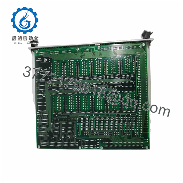
0100-76124
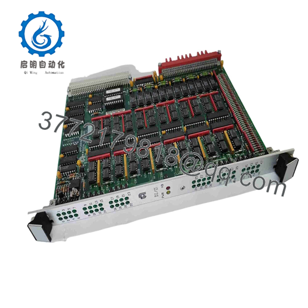
0100-76124
Frequently Asked Questions (FAQ)
Can the AMAT 0100-76124 be hot-swapped?
Do not assume it can. No reliable public documentation reviewed here establishes hot-swap capability for this exact assembly. Use the equipment-specific AMAT replacement procedure and place the system in the required maintenance state before removal.
What type of module is 0100-76124?
It should be treated as an Applied Materials equipment-specific electronic/control PCB. Public information is insufficient to establish a more specific functional classification with confidence.
Is 0100-76124 a PLC I/O module?
There is not enough reliable part-specific documentation to classify it as a conventional PLC digital or analog I/O module. Do not purchase a substitute based solely on a generic “I/O board” description.
What should I verify before purchasing a replacement?
At minimum, verify:
- Complete part number: 0100-76124
- PCB revision
- Applied Materials equipment/tool model
- Connector arrangement
- Existing board photographs
- Any additional assembly or revision markings
For a legacy AMAT spare, the equipment model is particularly important when confirming compatibility.
Will replacing the board erase the machine program?
Do not assume that it will. Whether configuration or firmware is stored on this particular board depends on the equipment architecture. Back up the applicable machine configuration before replacement and follow the OEM recovery procedure.
Is 0100-76124 obsolete?
I would not label it officially obsolete without authoritative Applied Materials lifecycle documentation. Marketplace availability does not establish OEM lifecycle status. For procurement, verify whether the offered unit is Factory Sealed, New Surplus, or Refurbished/Tested.
Why are exact photos important when ordering this part?
Because the public technical record for 0100-76124 is limited. A clear photograph of the PCB label, revision marking, connectors, and mounting arrangement can prevent a visually similar but electrically incompatible board from being supplied.



