
 WhatsApp: +86 16626708626
 Email:
  Phone: +86 16626708626
Description
3. Key Technical Specifications
| Parameter | Specification / Value |
| Part Number | 0190-27952 |
| Manufacturer | Applied Materials (AMAT) |
| Tool Compatibility | AMAT Producer, Endura, Centura 300mm Processing Racks |
| Assembly Type | Control & Interface Printed Circuit Board Assembly (PCBA) |
| Input Power | 24 V DC (Backplane System Power) |
| Signal Handling | Digital & Analog Subsystem Logic Routing |
| Form Factor | OEM Rack-Mount Card Module |
| Connector Type | Multi-Pin High-Density Backplane Connector |
| Operating Temperature | 10 to 50°C (50 to 122°F) |
| Storage Temperature | −20 to 70°C (−4 to 158°F) |
| Relative Humidity | 10% to 90% Non-Condensing |
4. Product Introduction & Supply Chain Strategy
This product is a Brand New Surplus unit. It is not used, not pulled from a decommissioned plant, and not refurbished. All modules undergo rigorous quality verification to ensure OEM-level reliability. The Applied Materials 0190-27952 acts as a primary control card designed for signal distribution, sub-bus management, and logic communication across AMAT mainframe platform racks.
Securing this part as New Surplus provides an immediate safety buffer against critical tool stoppages while controlling overall holding costs. Buying refurbished alternatives introduces unseen risks such as trace degradation, solder fatigue, or aged onboard capacitors. Factory-fresh surplus inventory guarantees long-term stability and protects high-value wafer production runs.
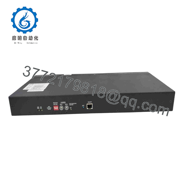
0190-27952
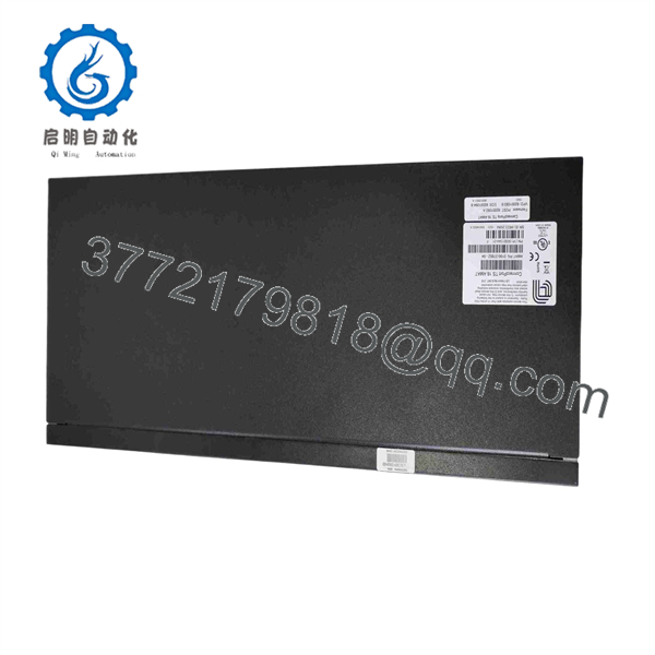
0190-27952
5. Installation & Configuration Guide
- Stage 1: Pre-Installation (Prep & Safety)
- Isolate system power by applying Lock-Out/Tag-Out (LOTO) protocols to the mainframe power distribution unit.
- Connect a verified ESD wrist strap to a verified chassis earth ground.
- Document all DIP switch positions, jumper settings, and cable connections on the old board.
- Stage 2: Removal
- Loosen the front panel retaining hardware with non-magnetic tools.
- Disengage the card ejectors simultaneously on the top and bottom to unseat the module cleanly from the backplane connectors.
- Stage 3: Installation (Clone & Seat)
- Verify that all jumper settings on the new 0190-27952 card duplicate the removed card configuration exactly.
- Carefully align the card with the card cage guide rails and push smooth until backplane connectors mate completely.
- Tighten thumb screws to establish proper chassis grounding and mechanical retention.
- Stage 4: Power-On & Testing
- Restore system logic power and check system status LEDs on the module front panel.
- Verify no communication errors or bus fault codes appear on the main operator station display.
- Perform diagnostic self-tests through the host software prior to initiating active process cycles.
6. Firmware/Software Versions & Upgrade Notes
- Recommended Firmware: Must be paired with system software builds matched to the tool configuration level.
- Compatibility Notice: Verify backplane revision and onboard logic chip combinations to ensure hardware handshaking compatibility.
- Upgrade Risks: Avoid flashing board firmware during a routine module replacement. Incompatible firmware can disrupt communication across system sub-busses and cause false interlock faults.
7. Frequently Asked Questions (FAQ)
Q: Is this 0190-27952 module genuine OEM and unused? A: Yes. This item is authentic New Surplus inventory obtained through original equipment supply channels. It has never seen service in a production fab and exhibits zero wear on gold contact pins.
Q: Why is New Surplus a better choice than a cheaper refurbished card? A: Refurbished semiconductor components carry hidden thermal stress and component aging. A single failure on a refurbished control board can cause tool shutdown, costing vastly more in lost wafer yield than any small initial savings on procurement.
Q: Is the 0190-27952 card hot-swappable during tool operation? A: No. Removing or inserting this board while power is applied can cause voltage spikes that damage backplane traces or logic chips on adjacent cards. Power down the rack card cage before replacement.
Q: How do I ensure correct communication after installation? A: Ensure all hardware DIP switches and configuration jumpers on the replacement board match the original unit precisely before seating it into the backplane.
Q: What warranty coverage applies to this board? A: This product includes a comprehensive 12-month operational warranty backed by strict pre-shipment visual, dimensional, and ESD safety inspection procedures.



