
 WhatsApp: +86 16626708626
 Email:
  Phone: +86 16626708626
Description
Key Technical Specifications
- Manufacturer: Applied Materials, Inc. (AMAT)
- Manufacturer Part Number: 0190-30354
- Product Type: Printed circuit board / equipment control board
- Associated Platform: AMAT Producer GT semiconductor-processing equipment
- Referenced Assembly Description: Producer GT UV Chamber Board
- Primary Application: Control or interface function within a UV chamber subsystem
- Installation Environment: AMAT semiconductor process-tool cabinet or chamber electronics assembly
- Replacement Basis: Match exact AMAT part number, board revision, connector population, and installed firmware or configuration
- Service Status: Legacy / discontinued spare part; stock depends on surplus availability
- ESD Handling: Required; use grounded wrist strap and static-safe work surface
- Power Verification: Confirm rack, backplane, and field-supply voltages against the tool electrical drawings before installation
- Documentation Requirement: Verify compatibility using the Producer GT tool BOM, schematic, and AMAT service documentation before ordering
Product Introduction
The AMAT 0190-30354 is an Applied Materials Producer GT UV chamber printed circuit board used in semiconductor manufacturing equipment. It is a tool-specific replacement board, not a general-purpose PLC or universal industrial controller. The exact part number must match the installed board and the equipment bill of materials.
Buyers select AMAT 0190-30354 when an installed Producer GT UV chamber board has a confirmed hardware fault or physical damage. Verify board revision, connector layout, installed jumpers, labels, and any device-specific configuration before swapping it into a production tool. Public listings identify it as a Producer GT UV chamber PCB, but they do not provide an OEM electrical datasheet; do not rely on unverified third-party descriptions that label it as an RF matcher, pressure sensor, or temperature controller.
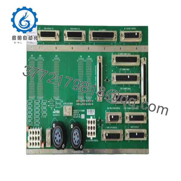
0190-30354
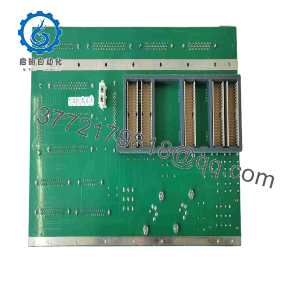
0190-30354
Troubleshooting Quick Reference
| Symptom | Possible Cause | Relevance to this Part | Quick Check Method | Recommendation |
|---|---|---|---|---|
| No board LEDs or no response after power-up | Missing cabinet supply, blown fuse, open interlock, damaged backplane connector | ⚠️ Medium | With the tool safely isolated, measure the specified supply rails at the board connector using a calibrated Fluke 115 or equivalent; compare readings with the AMAT schematic | Check power supplies, fuses, interlocks, and connector seating before replacing the board |
| Chamber subsystem reports communication timeout | Loose harness, wrong node/address setting, damaged network cable, firmware mismatch, failed board interface | ✅ High | Inspect all keyed connectors; compare old-board labels and switch positions; review controller diagnostic logs and tool event history | Document settings before removal; replace the board only after verifying the network and upstream controller |
| UV chamber does not complete initialization | Door or safety interlock open, external subsystem fault, missing utility, corrupted board configuration | ⚠️ Medium | Review the startup sequence and interlock status in the tool diagnostics; check related chamber I/O and safety-chain indications | Correct the external fault first; do not condemn the PCB solely from an initialization failure |
| Intermittent faults after chamber heating or extended production | Cracked solder joint, connector fretting, marginal power rail, thermal stress, failing adjacent module | ✅ Medium | Run the system under normal load; inspect for fault recurrence as cabinet temperature rises; check for discoloration, damaged capacitors, or connector heating | If the fault follows the board after harness and supply checks, replacement is justified |
| Alarm appears immediately after replacement | Board revision mismatch, incorrect jumper/DIP setting, incompatible firmware, connector not fully seated | ✅ High | Photograph the original board before removal; compare revision labels, jumper positions, daughterboards, and all connector positions | Reinstall only after matching the physical configuration exactly; request a compatible revision when ordering |
| I/O or chamber device remains inactive | Failed valve, lamp, sensor, relay, field wiring, interlock logic, separate I/O module fault | ❌ Low to Medium | Check field-device voltage and continuity at the terminal or interface point; compare command versus feedback in diagnostics | Troubleshoot the field circuit and adjacent I/O hardware before replacing 0190-30354 |
| Visible corrosion, overheated components, burn marks, or liquid contamination | Environmental damage or electrical event | ✅ High | Perform a power-off visual inspection under adequate lighting; inspect connector pins and PCB areas around power components | Do not energize a visibly damaged board; replace it and investigate the root cause before installing the replacement |
| Tool runs but produces recurring chamber-related faults | Marginal board performance, unstable supply, grounding issue, shielding error, process hardware fault | ⚠️ Medium | Capture diagnostic logs, alarm timestamps, supply measurements, and photos of the installed board | Contact technical support with photos, tool serial number, board labels, and diagnostic logs before authorizing a replacement |
❗ Before replacing this board: verify the tool’s supply rails, interlocks, harnesses, and diagnostics first. In semiconductor tools, a board is often blamed when the actual fault is a loose connector, failed field device, cabinet power issue, or incompatible replacement revision.
❗ ESD warning: use a grounded wrist strap, static-safe mat, and antistatic packaging. I have seen expensive control boards damaged before installation because someone handled them on a dry shop floor without ESD protection. Take a photo of every connector, label, jumper, and switch setting before you touch anything. Seriously.
Keep these checks in mind and you will save yourself most of the usual rework time. If you are stuck, provide technical support with clear board photos, the complete AMAT label information, tool diagnostics, and the old board’s revision details.
Frequently Asked Questions
Is AMAT 0190-30354 a direct replacement part?
It can be a direct replacement only when the installed board carries the exact AMAT 0190-30354 part number and has a compatible revision, connector layout, and configuration. “Looks similar” is not enough for an AMAT chamber board. Check the equipment bill of materials, board revision label, jumper settings, and tool documentation before purchase.
What equipment uses AMAT 0190-30354?
Public surplus listings identify AMAT 0190-30354 as a PCB associated with an Applied Materials Producer GT UV chamber. Because public technical data is limited and conflicting reseller pages assign unrelated functions to this number, confirm the installed application from your tool records or OEM documentation rather than relying on generic online descriptions.
Can I hot-swap this board?
No. Treat AMAT 0190-30354 as a non-hot-swappable board unless the specific AMAT service procedure explicitly says otherwise. Shut down and isolate the relevant equipment power, follow site lockout/tagout procedures, allow stored energy to dissipate, and use ESD controls. Hot-swapping a legacy chamber board can damage the board, connector, backplane, or related electronics.
Will the programming or configuration remain after a board swap?
Do not assume it will. Configuration may reside in the host controller, on the board, in nonvolatile memory, or in physical jumpers and DIP switches. Photograph the old board’s switch and jumper positions, collect tool logs, and back up the applicable tool configuration before removal. If the board contains site-specific firmware or calibration data, you may need AMAT-approved recovery procedures after installation.
Why does a replacement board cause a communication error even though it powers up?
Firmware or revision mismatch is a common reason. I have seen technicians replace a healthy-looking board and spend two days chasing a communication timeout because the replacement’s revision did not match the controller expectation. Compare assembly revision labels, installed firmware identifiers where accessible, and all physical configuration settings before installing the replacement.
Is this part obsolete, and is stock limited?
This is a legacy AMAT spare part and is commonly offered through surplus channels rather than as a current catalog item. Availability can change quickly, so confirm the exact condition, quantity, photographs, revision, and lead time before issuing a purchase order.
Is the unit New Original / New Surplus or Refurbished?
The condition must be stated on the specific quotation or listing. For a New Original / New Surplus unit, request photos of the OEM label, packaging, serial or traceability labels where available, connector condition, and any included documentation. For a Refurbished (tested) unit, request the test scope, test fixture used, test report, repair history, and warranty terms.
Why can surplus stock cost less than a factory replacement?
Surplus inventory may come from unused project stock, decommissioned tool spares, excess inventory, or liquidation channels. Lower price does not automatically mean lower quality, but it does mean you need documentation. Ask for high-resolution photos, part and revision confirmation, packaging condition, test results, warranty coverage, and a clear return procedure before buying.



