
 WhatsApp: +86 16626708626
 Email:
  Phone: +86 16626708626
Description
3. Key Technical Specifications
| Parameter | Value |
|---|---|
| Manufacturer | Applied Materials (AMAT) |
| AMAT Part Number | 0190-51414 |
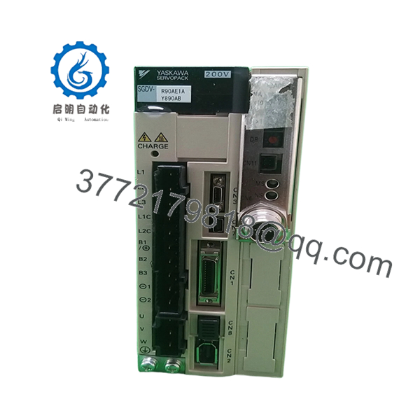
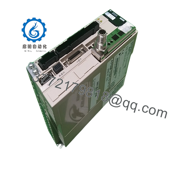
| Associated OEM Drive | Yaskawa SGDV-R90AE1AY890AB |
| Product Type | AC Servo Drive Assembly |
| Servo Platform | Yaskawa Sigma-V Series |
| Application | Semiconductor Equipment Motion Control |
| Motor Control Type | Digital Servo Control |
| Installation Environment | Cleanroom Tool Controller Cabinet |
| Cooling Method | Forced-Air Cabinet Cooling |
| Interface Type | OEM Integrated Motion Control Interface |
| Mounting Style | Cabinet-Mounted Servo Pack |
| Typical Equipment Use | Wafer Handling and Process Motion Axes |
| OEM Integration | Applied Materials Tool-Specific Configuration |
| System Category | Semiconductor Manufacturing Equipment |
| Availability Status | Obsolete OEM Spare Part |
| Service Condition | New Surplus or Refurbished Inventory |
The AMAT 0190-51414 appears in Applied Materials spare-parts inventories as a Yaskawa Sigma-V servo drive assembly using the SGDV-R90AE1AY890AB drive platform. It is typically deployed inside semiconductor processing tools where precise axis control, wafer transport positioning, and chamber automation require deterministic servo performance.
4. Product Introduction
The AMAT 0190-51414 is an Applied Materials servo drive assembly built around a Yaskawa SGDV-R90AE1AY890AB Sigma-V SERVOPACK platform. It is used within semiconductor fabrication equipment to control precision motion axes associated with wafer handling, transfer robotics, and process module positioning.
In field support situations, the challenge is usually not the drive hardware itself but maintaining compatibility with the machine configuration, encoder feedback parameters, and OEM commissioning files. Engineers replacing this assembly should verify all machine-specific servo settings before installation to avoid positioning faults and unexpected interlocks.
- 0190-51414
- 0190-51414
5. Installation & Configuration Guide
Stage 1: Pre-Installation Preparation (10 Minutes)
⚠️ Safety First
- Notify production and maintenance teams of equipment downtime.
- Place the semiconductor tool into maintenance mode.
- Execute lockout/tagout procedures.
- Verify stored energy discharge.
- Wait at least 5 minutes before opening servo cabinets.
Tools Required
- Grounded ESD wrist strap
- PH1 screwdriver
- Fluke 115 multimeter
- Torque screwdriver
- Wire labels
- Smartphone for documentation
- ESD work mat
Data Backup
- Export current servo parameter files.
- Save controller configuration backups.
- Record:
- Axis assignments
- Encoder settings
- Node addresses
- Servo tuning values
- Photograph:
- Terminal wiring
- Encoder connections
- Communication ports
- Grounding points
❗ Document every parameter before touching the drive. I’ve seen a replacement servo installed perfectly, then sit offline for eight hours because nobody backed up the original tuning values.
Stage 2: Removing the Old Module (10 Minutes)
- Open the electrical cabinet.
- Label all motor and feedback cables.
- Disconnect:
- Power wiring
- Encoder feedback
- Communication cables
- Ground connections
- Remove mounting hardware.
- Extract the servo pack carefully.
⚠️ Never pull encoder connectors by the cable body. The connector may survive. The cable usually does not.
- Inspect:
- Cabinet contamination
- Cooling airflow path
- Connector condition
- Ground bonding
⚠️ Important
Keep the original drive available until motion testing completes successfully.
Stage 3: Installing the New Module (10 Minutes)
1. ESD Preparation
- Wear grounded wrist strap.
- Verify exact model identification:
- AMAT 0190-51414
- SGDV-R90AE1AY890AB
2. Configuration Clone (Critical)
Transfer:
- Servo parameters
- Encoder settings
- Motion limits
- Acceleration profiles
- Communication configuration
❗ This is one of the easiest ways to create a major startup problem. Factory defaults rarely match the machine. Always clone the original configuration whenever possible.
3. Mount the Drive
- Install mounting hardware.
- Verify mechanical stability.
- Confirm cooling clearance.
- Verify grounding continuity.
4. Reconnect Wiring
- Reconnect motor power cables.
- Reconnect encoder wiring.
- Restore communication interfaces.
- Tighten terminals to specified torque.
Self-Checklist
- Model verified
- Parameters backed up
- Encoder wiring confirmed
- Ground connected
- Power terminals secure
- Cooling path unobstructed
Stage 4: Power-On & Testing (15-20 Minutes)
Pre-Power Check
- Verify ground continuity.
- Check DC bus resistance.
- Verify no phase-to-ground short exists.
Power-Up Procedure
- Energize cabinet power.
- Observe servo drive startup indicators.
- Connect commissioning software.
- Verify:
- Drive recognition
- Encoder feedback
- Communication status
- Alarm history
- Restore parameter set if required.
- Perform low-speed jog testing.
- Verify homing sequence.
- Validate motion positioning accuracy.
⚠️ Troubleshooting Note
- Servo Alarm Immediately After Startup: Check encoder configuration.
- Communication Fault: Verify node addressing and fieldbus settings.
- Position Error Alarm: Verify feedback scaling and motor pairing.
- Drive Trips Under Motion: Check acceleration parameters and mechanical load.
Common Field Pitfalls Engineers Encounter
❗ Firmware and Parameter Mismatch
Many replacement failures are configuration issues, not hardware faults.
I worked a wafer-transfer robot replacement where the new drive powered up normally but generated axis following errors. The problem was a mismatched servo parameter file.
Avoidance: Backup parameters before removal and restore verified settings after installation.
❗ Encoder Configuration Errors
Servo drives depend heavily on encoder setup.
A single incorrect feedback parameter can create unstable motion or prevent startup entirely.
Avoidance: Record encoder model and configuration before replacement.
❗ Motor-to-Drive Pairing Issues
Not every Sigma-V drive configuration is interchangeable.
Even if the hardware appears identical, motor tuning files may differ.
Avoidance: Verify complete motor-drive compatibility before energizing.
❗ Power Supply Loading
Servo systems can draw substantial startup current.
I’ve seen replacement drives trip cabinet breakers because the original installation already operated close to power limits.
Avoidance: Verify available supply capacity and maintain at least 20% margin.
❗ Electrostatic Discharge (ESD)
Motion-control electronics are particularly vulnerable during installation.
I once watched a technician unpack a servo assembly directly onto a painted cabinet top during winter. The drive powered up but failed communication diagnostics immediately afterward.
That became a very expensive lesson.
Avoidance: Ground strap, ESD mat, anti-static handling at every step.
Keep these checks in mind and you’ll save yourself 90% of typical rework time.
6. Frequently Asked Questions (FAQ)
Q1. Is AMAT 0190-51414 a complete servo drive or just a PCB?
Based on available spare-parts references, the 0190-51414 is associated with a Yaskawa SGDV-R90AE1AY890AB servo drive assembly rather than a standalone control PCB. Verify the exact supplied scope before purchase because surplus inventory can vary.
Q2. Can I hot-swap this drive?
No.
Power down the equipment first.
Removing servo hardware under power risks DC bus damage, encoder faults, and controller communication alarms.
Q3. Is AMAT 0190-51414 obsolete?
Yes.
This is typically sourced from surplus semiconductor equipment inventory, spare-part programs, or refurbished stock rather than current OEM production channels.
Q4. Will I lose motion parameters when replacing the drive?
Possibly.
Many semiconductor tools store portions of axis configuration within the drive itself.
Always export parameter files before removal.
Never assume the replacement drive contains matching settings.
Q5. Why are some units sold much cheaper than others?
Condition varies significantly.
You may encounter:
- Untested surplus inventory
- Removed working spares
- Refurbished units
- Fully tested assemblies
Some listings specifically state the hardware is sold “as-is” without testing or warranty. Review the condition carefully before purchasing.
Q6. What testing should be completed before shipment?
A proper supplier should perform:
- OEM label verification
- Visual inspection for repairs or corrosion
- Power-on testing
- Servo communication testing
- Encoder interface verification
- Alarm diagnostics review
- 24-hour load operation
- 500 V insulation resistance testing (>10 MΩ)
- Firmware documentation
- Final QC sign-off
Test reports and startup videos should be available upon request.
Q7. What is the biggest installation mistake engineers make with servo replacements?
Parameter loss.
Honestly, hardware failures are less common than configuration mistakes.
A technician removes the original drive, installs the replacement, then discovers nobody saved the motion parameters.
Now the machine cannot home correctly, positioning is off, and production is still down.
Always back up the drive before touching a single connector. That one step prevents most commissioning headaches.


