
 WhatsApp: +86 16626708626
 Email:
  Phone: +86 16626708626
Description
Key Technical Specifications
| Parameter | Value |
|---|---|
| Model Number | 117417-01 |
| Manufacturer | AMETEK Dynamic Fluid Solutions / Windjammer |
| Product Type | Brushless centrifugal blower |
| Frame Size | 5.7 in. / 145 mm |
| Supply Voltage | 120 V AC |
| Motor Type | Windjammer brushless motor |
| Output Configuration | Bypass, tangential discharge |
| Fan Stages | 3 |
| Power Level | 800 W |
| Speed Control | 0–10 V DC analog command |
| Speed Regulation | Closed-loop electronic speed regulation |
| Maximum Airflow | 82.51 SCFM / 38.92 L/s / 140.18 m³/h |
| Maximum Pressure | 127.33 in. H₂O / 31.68 kPa / 316.85 mbar |
| Inlet Tube Diameter | 1.25 in. |
| Electrical Connector | 5-cavity post header |
| Connector Assemblies | AMETEK 5-39021 and 39796 |
| Compliance | RoHS and REACH compliant |
| Typical Applications | Medical and dental equipment, material handling, air sampling, fume evacuation, packaging, and printing equipment |
The manufacturer identifies the 117417-01 as a 120 V AC, three-stage, 800 W Windjammer brushless blower with a 0–10 V DC speed-control input. A distributor listing specifies 82.51 SCFM maximum flow and 127.33 in. H₂O maximum pressure for this exact part number.
Product Introduction
The AMETEK Windjammer 117417-01 is a 5.7 in. brushless centrifugal blower for equipment requiring electronically controlled, high-pressure airflow or vacuum. It operates from 120 V AC and uses a 0–10 V DC command signal for closed-loop speed control. Typical applications include fume-extraction equipment, air-sampling systems, vacuum handling, medical devices, packaging machinery, and industrial process equipment.
The key selection point is its pressure capability: this three-stage, 800 W blower is designed for restrictive air paths where a conventional axial fan will not maintain usable flow. It delivers up to 82.51 SCFM and 127.33 in. H₂O maximum pressure, with a 1.25 in. inlet and a five-cavity electrical connection.
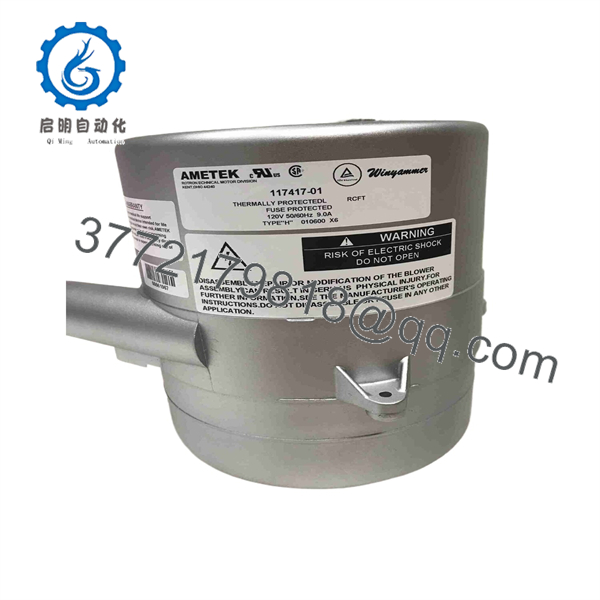
117417-01
Troubleshooting Quick Reference
| Symptom | Possible Cause | Relevance to This Part | Quick Check Method | Recommendation |
|---|---|---|---|---|
| Blower does not start | No 120 V AC supply, blown fuse, open interlock, failed connector, failed motor electronics | ✅ High | Measure the supply voltage at the blower power leads using a true-RMS multimeter. Verify the machine fuse, contactor, emergency-stop circuit, and connector engagement. | Confirm a stable 120 V AC supply before replacing the blower. Do not energize exposed terminals. |
| Blower starts but runs at minimum speed | Missing or low 0–10 V DC command, incorrect analog-common connection, control output fault | ✅ High | Measure the speed-command signal at the command terminals while changing the machine setpoint. Confirm the signal rises from approximately 0 V toward 10 V DC. | Check PLC, controller, potentiometer, and analog-common wiring before replacing the blower. |
| Blower runs at full speed regardless of command | Open 0–10 V command wire, failed analog output, incorrect signal reference, controller fault | ✅ Medium | Measure the command voltage directly at the blower connector. Compare the reading to the machine command value. | Repair the command circuit first. A disconnected analog input can cause some blower-control designs to default to a fixed speed. |
| Low airflow or weak vacuum | Blocked filter, collapsed hose, restricted inlet, clogged silencer, leaking duct, worn impeller | ✅ Medium | Measure pressure or airflow at the machine test point. Inspect filters, hoses, inlet tube, exhaust path, and vacuum seals. | Correct restrictions and leaks before replacing the blower. A dirty filter can make a good 117417-01 look underpowered. |
| Blower overheats or shuts down after several minutes | Blocked cooling path, excessive backpressure, high ambient temperature, failed external cooling fan | ✅ Medium | Inspect air passages and filters. Check cabinet temperature and verify the application does not exceed the blower’s intended pressure/flow operating envelope. | Remove the restriction and correct thermal conditions. Do not repeatedly cycle power to defeat a thermal protection event. |
| Excessive vibration or rattling | Loose mounting, damaged impeller, foreign object, worn bearing assembly, cracked housing | ✅ High | Disconnect power and wait for full stop. Inspect mounting screws, housing, inlet, discharge, and impeller area for debris or impact damage. | Replace the blower if the impeller contacts the housing, bearing noise persists, or the housing is cracked. |
| Blower trips breaker or fuse | Shorted wiring, failed motor drive electronics, wrong protective device, damaged cable | ✅ High | Inspect the cable for abrasion and measure insulation resistance with the blower isolated from sensitive electronics. Check inrush and running current with a clamp meter. | Do not install a larger fuse to mask the fault. Replace the blower only after confirming cable and machine wiring are sound. |
| Airflow drops only at high machine demand | Ducting undersized, filter loading, leakage under vacuum, process restriction, speed command limited below 10 V | ❌ Low | Trend the analog command and measure differential pressure across filters and process restrictions at maximum demand. | Review duct sizing and process restriction. Confirm the controller actually commands the required speed. |
| Replacement blower does not fit or connect | Wrong inlet orientation, missing mating connector, incorrect mounting pattern, incompatible harness | ✅ High | Compare the old and replacement units side by side: inlet diameter, discharge direction, mounting, cable length, and connector pin arrangement. | Verify the 1.25 in. inlet and required mating connector assemblies before ordering. |
❗ Verify the control signal before replacing the blower. This model uses a 0–10 V DC speed command. If the PLC analog output is stuck at 2 V, the blower may behave exactly as commanded: it will run slowly, not necessarily fail. Measure the signal at the blower connector, not only at the PLC cabinet.
❗ Do not judge performance by sound alone. A three-stage blower can sound normal while a plugged filter, collapsed hose, or leaking vacuum connection prevents the machine from reaching pressure. Check actual pressure and flow at the equipment test point.
❗ Photograph the wiring and connector before removal. The 117417-01 uses a five-cavity post-header arrangement with power leads and speed-command connections. Swapping control wiring or losing the analog-common reference can cause no-start, fixed-speed, or unstable operation.
❗ Keep fingers, tools, and loose wire clear of the inlet and discharge. This is an 800 W high-speed blower. Isolate electrical power and wait until the impeller fully stops before inspecting the airflow path.
If you are stuck, send technical support photos of the nameplate, connector, wiring colors, speed-command measurement, supply-voltage measurement, pressure reading, filter condition, and application ducting. Keep these checks in mind and you will save yourself 90% of typical rework time.
Frequently Asked Questions (FAQ)
Is the AMETEK 117417-01 a 120 V AC blower?
Yes. The manufacturer lists the 117417-01 as a 120 V AC Windjammer blower with a three-stage brushless motor and an 800 W power level. Confirm the voltage on the product nameplate before installation because other Windjammer models are available in different voltage and control configurations.
How is blower speed controlled?
The 117417-01 uses a 0–10 V DC analog speed-control command with closed-loop speed regulation. In a typical machine, a PLC analog output, dedicated motion controller, or potentiometer supplies the command. Verify the speed-command wiring, signal reference, and actual voltage at the blower connector before concluding that the motor has failed.
What airflow and pressure can this blower provide?
For this specific part number, a distributor lists maximum performance of 82.51 SCFM, 38.92 L/s, or 140.18 m³/h, with maximum pressure of 127.33 in. H₂O, 31.68 kPa, or 316.85 mbar. Actual installed performance will be lower or different depending on duct size, filters, hose restrictions, leakage, altitude, and the 0–10 V command level.
Can I use this blower for vacuum service?
Yes. The 117417-01 uses a bypass output configuration and is intended for high-pressure airflow and vacuum-generating applications. The manufacturer’s product family covers applications such as air sampling, fume evacuation, material handling, medical equipment, and packaging machinery. Confirm that your hose, filtration, seals, and process material are suitable for the required vacuum level and airflow.
Can I replace it with another 5.7 in. blower?
Not automatically. The frame size alone does not establish interchangeability. Match the 120 V AC supply, 800 W power class, three-stage design, bypass configuration, pressure-flow curve, mounting geometry, inlet diameter, discharge orientation, five-cavity connector, and 0–10 V closed-loop control scheme. A physically similar blower may run but fail to meet the machine’s airflow or pressure requirement.
Does the blower include the mating electrical connector?
The manufacturer lists connector assemblies 5-39021 and 39796 in the product attributes for this model, and a distributor states that the blower is packaged with those mating connector assemblies. Confirm the exact contents of the quoted unit before purchase, especially for New Surplus or open-box inventory.
How long should the 117417-01 last?
A distributor states that Windjammer brushless blowers can operate for up to 20,000 hours of continuous duty, but actual life depends on inlet filtration, duty cycle, operating pressure, ambient temperature, contamination, vibration, and maintenance. Do not treat 20,000 hours as a guaranteed life for every installation. Monitor airflow, current draw, vibration, and filter differential pressure in critical equipment.
Why is New Surplus stock cheaper than factory-channel inventory?
New Surplus units often originate from canceled OEM builds, maintenance inventory, distributor overstock, or equipment redesigns. The lower price can be legitimate, but verify the date code, packaging, nameplate, inlet and discharge condition, connector contents, evidence of storage damage, warranty, and return process. For an electronically controlled blower, request confirmation that the unit was powered and checked through its 0–10 V command range before shipment.



