
 WhatsApp: +86 16626708626
 Email:
  Phone: +86 16626708626
Description
Key Technical Specifications
| Parameter | Specification |
|---|---|
| Manufacturer | Applied Materials |
| Part number | 0010-23715 |
| Product name | PMAX Emissometer RTP Probe Assembly |
| Equipment family | PMAX |
| Product category | Semiconductor process / measurement equipment component |
| Measurement function | Wafer emissivity measurement |
| Probe type | Emissometer probe assembly |
| Process association | RTP / rapid thermal processing |
| Revision documented in field inventory | REV:002 |
| Electrical interface | Verify from equipment documentation |
| Optical configuration | Verify from equipment documentation |
| Measurement wavelength/range | Not reliably published for exact P/N |
| Operating temperature | Not reliably published for exact P/N |
| Dimensions | Not reliably published for exact P/N |
| Weight | Approx. 0.5 kg reported for a pre-owned assembly; configuration may vary |
| Replacement status | Legacy / field-service spare |
An equipment listing records the exact unit as REV:002, while a separate inventory record explicitly describes 0010-23715 as the PMAX emissometer probe assembly.
Important specification warning: I found conflicting online descriptions that incorrectly classify 0010-23715 as a power-supply module, RF interface board, or chamber component. Those descriptions should not be used for technical procurement. The stronger exact-part-number evidence consistently identifies 0010-23715 as the PMAX Emissometer / Emissometer RTP Probe Assembly.
The exact optical specifications, electrical pinout, calibration constants, and PMAX tool compatibility should therefore be taken from the applicable Applied Materials service documentation or the installed tool’s configuration record rather than inferred from similar AMAT probe assemblies.
Product Introduction
The Applied Materials 0010-23715 is identified as a PMAX Emissometer RTP Probe Assembly used in semiconductor manufacturing equipment. Its primary measurement role is associated with wafer emissivity during rapid thermal processing, where emissivity information is important for interpreting non-contact thermal measurements.
This is a specialized equipment spare, not a general-purpose industrial sensor. Replacement should be controlled by the complete AMAT part number, revision, physical configuration, calibration requirements, and the specific PMAX tool configuration. A current equipment listing also identifies a REV:002 version of the assembly.
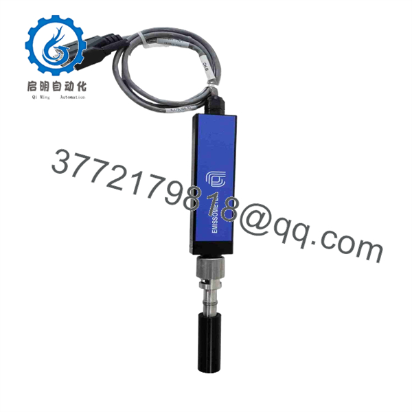
0010-23715
Installation & Configuration Guide
Stage 1 — Pre-Installation
Estimated time: 30–60 minutes
- Place the semiconductor tool in the approved maintenance state.
- Follow the site’s equipment shutdown procedure for the PMAX system.
- Disable applicable process heating and thermal-processing functions.
- Apply the required electrical and process-energy isolation procedures.
- Allow the chamber and probe area to reach the specified maintenance condition.
- Use appropriate ESD controls when handling electrical portions of the assembly.
- Record the existing part number, revision, cable routing, connector orientation, and physical mounting position.
- Back up or document the applicable PMAX measurement and calibration configuration before removal.
⚠️ Do not treat the emissometer as a simple temperature probe. Its measurement chain and calibration relationship are part of the thermal-control system.
Stage 2 — Remove the Existing Probe Assembly
Estimated time: 30–60 minutes
- Confirm that the equipment is in the approved maintenance state.
- Photograph the installed probe, mounting hardware, connector orientation, and cable routing.
- Disconnect the assembly using the AMAT-approved procedure.
- Protect optical and sensing surfaces from contamination.
- Remove the mounting hardware without applying excessive force to the probe.
- Place the removed assembly in an ESD-safe and contamination-controlled container.
- Compare the removed unit’s part number and revision with the replacement.
⚠️ Semiconductor thermal-processing equipment is highly sensitive to contamination. Do not touch optical or sensing surfaces with bare hands.
Stage 3 — Install the 0010-23715
Estimated time: 30–60 minutes
- Verify the replacement label reads 0010-23715.
- Check the revision against the removed assembly and the PMAX equipment documentation.
- Inspect the probe tip, optical surfaces, cable, connectors, and mounting hardware.
- Install the probe in the original orientation.
- Confirm mechanical seating without forcing the assembly.
- Reconnect the cable exactly as documented.
- Verify that cable routing does not introduce mechanical stress or interference.
- Confirm that the probe has the required process-chamber clearance.
- Check that no foreign material has entered the measurement path.
For used equipment, request photographs of the actual probe before purchase. One current listing for 0010-23715 identifies the item as a used PMAX Emissometer sensor probe and states that the photographs represent the actual unit.
Stage 4 — Verification and Calibration
Estimated time: 30–120 minutes, depending on PMAX configuration
- Restore the equipment according to the AMAT maintenance procedure.
- Check for connector, sensor, or probe-related alarms.
- Verify that the PMAX controller recognizes the measurement assembly.
- Confirm the baseline measurement with the equipment in its approved verification state.
- Perform the applicable emissivity/thermal calibration procedure.
- Compare the measured value against the qualified reference standard.
- Run a controlled thermal cycle without production material where the maintenance procedure permits.
- Check measurement stability throughout the cycle.
- Confirm that the thermal-control system receives valid measurement data.
- Record the replacement part number, revision, calibration status, and service date.
⚠️ Do not return the tool to production solely because the probe is electrically recognized. Measurement verification and calibration are required before relying on the assembly for process control.
FAQ
What is Applied Materials 0010-23715?
0010-23715 is a PMAX Emissometer RTP Probe Assembly used in Applied Materials semiconductor equipment. Independent equipment inventories consistently associate the part with the PMAX emissometer system.
What does an emissometer probe measure?
An emissometer is used to determine surface emissivity, which is important when interpreting non-contact thermal measurements from wafer surfaces. The exact measurement architecture and calibration method depend on the PMAX equipment configuration.
Is 0010-23715 a pyrometer?
It should not be automatically classified as a conventional pyrometer. Current equipment records identify 0010-23715 specifically as a PMAX Emissometer, while another AMAT part, 0010-23716, is separately listed as a PMAX pyrometer/emissometer probe.
What revision should I order?
At least one identified field unit is marked REV:002. Do not assume every 0010-23715 assembly has the same revision. Match the replacement against the existing equipment documentation and the installed unit.
Can a used 0010-23715 be installed directly?
Not without verification. Used units exist in the secondary market, including examples removed from working service. Before installation, inspect the probe and cable, verify the revision, and perform the required measurement/calibration checks.
What should procurement verify before purchasing?
Request the complete 0010-23715 part number, revision, actual-unit photographs, condition, probe/cable integrity, and test or calibration documentation. For semiconductor equipment, these details are more useful than a generic statement that the part is “compatible.”
Are detailed electrical and optical specifications publicly available?
I could not verify authoritative public specifications for the exact 0010-23715 covering wavelength, electrical pinout, calibration constants, operating temperature, or dimensional tolerances. Those values should be obtained from the applicable Applied Materials service documentation rather than copied from similar PMAX probe models.



