
 WhatsApp: +86 16626708626
 Email:
  Phone: +86 16626708626
Description
Key Technical Specifications
| Parameter | Specification |
| Manufacturer | Applied Materials (AMAT) / AKT |
| Part Number | 0100-71313 |
| Compatible Platforms | AKT 15K, 25K, 55K, and 60K CVD/PECVD Toolsets |
| Bus Standard | VMEbus Standard Architecture (6U Form Factor) |
| Power Requirements | +5 V DC, ±12 V DC (Supplied via VME Backplane) |
| Functional Application | Chamber sensor data acquisition and subsystem signal processing |
| Operating Temperature | 0°C to +60°C (32°F to 140°F) |
| Storage Temperature | −20°C to +85°C (−4°F to 185°F) |
| Board Construction | Multi-layer PCB with conformal coating & ESD-safe logic ICs |
| Backplane Interconnect | Dual 96-pin DIN VME backplane connectors (P1/P2) |
Product Introduction & Supply Chain Strategy
This product is a Brand New Surplus unit. It is not used, not pulled from a decommissioned fab tool, and not refurbished. All modules undergo rigorous quality verification to ensure OEM-level reliability. The Applied Materials 0100-71313 VME I/O Controller Board manages real-time sensor communications, valve actuation signals, and feedback loops between AKT processing chambers and the mainframe control computer.
From a Total Cost of Ownership (TCO) perspective, securing a verified New Surplus 0100-71313 module is a vital buffer against unscheduled fab stops. Because original OEM manufacturing for legacy AKT VMEbus architectures has ceased, relying on spot-market repairs or pulled parts risks intermittent signal drift and premature failure. Maintaining 1 unit in safety stock eliminates lead time variability while protecting against wafer misprocessing costs that can easily exceed $100,000 per tool failure.
Installation & Configuration Guide
Stage 1: Pre-Installation (Prep & Safety)
- Perform Lock-Out/Tag-Out (LOTO) procedures on the main tool power breaker and card cage cabinet.
- Put on a grounded ESD wrist strap connected to the fab tool ground chassis.
- Photograph all onboard DIP switch blocks, jumper placements, and piggyback daughtercards on the board being replaced.
Stage 2: Removal
- Unfasten the retaining screws at the top and bottom of the VME module faceplate.
- Flip the upper and lower ejector handles outward simultaneously to unseat the 96-pin DIN connectors from the backplane.
- Slide the 0100-71313 straight out along the chassis rails, placing it immediately inside an ESD-shielded bag.
Stage 3: Installation (Clone & Seat)
- Configure all DIP switches and jumper blocks on the new 0100-71313 board to mirror the original unit’s base address and interrupt levels exactly.
- Align the PCB edges with the card guide channels inside the VME chassis.
- Slide the board inward until the backplane connectors touch, then press the ejector handles inward until the board locks flush with the frame. Secure the faceplate screws.
Stage 4: Power-On & Testing
- Check backplane voltage rails (+5 V DC and ±12 V DC) for low impedance or shorts prior to re-energizing the rack.
- Restore power to the VME chassis and verify that the front-panel green PWR/READY LED stays solid while ERR/FAULT remains dark.
- Launch the tool diagnostic software to perform a communication handshake check and confirm full I/O mapping across active chamber channels.
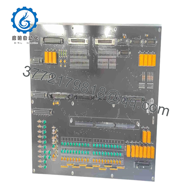
0100-71313
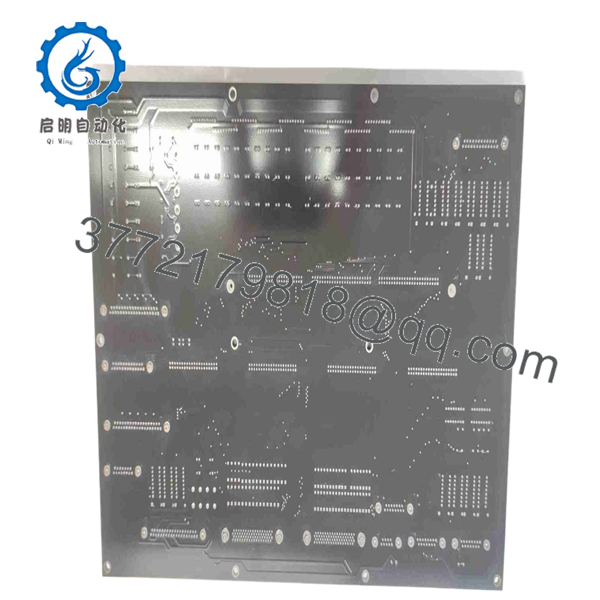
0100-71313
Firmware/Software Versions & Upgrade Notes
- Recommended Baseline: Revision-matched to existing tool software release (e.g., System Software V4.x/V5.x).
- Compatibility Considerations: While the physical 6U 0100-71313 board layout remains consistent, onboard EPROMs carry specific firmware for addressing sub-controllers. Mismatches between the board firmware and main tool software can trigger system initialization errors.
- Firmware Swap Warning: Prior to physical swap-out, transfer socketed EPROM/EEPROM chips from the original board to the new assembly if custom fab calibration tables are stored locally. Do not flash firmware updates during a hardware replacement while the tool is holding vacuum or actively processing production lots.
Frequently Asked Questions (FAQ)
Is this Applied Materials 0100-71313 board truly New Surplus?
Yes. This module is 100% Genuine New Surplus. It has never seen runtime hours inside a semiconductor or display fab and has been preserved in anti-static storage. We maintain a zero-tolerance policy against second-hand, pulled, or refurbished components.
Why pay more for New Surplus instead of a cheaper refurbished 0100-71313?
Refurbished semiconductor circuit boards often harbor micro-fractures, degraded electrolytic capacitors, or latent ESD damage from improper cleanroom handling. Investing in New Surplus guarantees factory-original component integrity, avoiding catastrophic tool crashes that dwarf initial procurement savings.
What is the lifecycle availability for the AMAT 0100-71313?
The 0100-71313 is an obsolete OEM part as Applied Materials has transitioned to newer control platforms. Global New Surplus inventory is finite, making this board an essential item for strategic last-time-buys or safety-stock buffers for mature AKT production lines.
Can I perform a hot-swap on this VME controller card?
No. Unplugging or inserting a VMEbus board while the backplane is energized creates inductive voltage spikes that can permanently destroy fragile CMOS logic gates on the board and adjacent system cards. Always power down the VME chassis first.
What warranty coverage is included with this unit?
Unlike standard 30-day warranties offered on used components, our New Surplus 0100-71313 board comes with a full 1-year functional replacement warranty, supported by comprehensive ESD-safe functional testing records prior to shipment.



