
 WhatsApp: +86 16626708626
 Email:
  Phone: +86 16626708626
Description
Key Technical Specifications
| Parameter | Specification |
| Manufacturer | Applied Materials (AMAT) / AKT |
| Part Number | 0100-77037 |
| System Compatibility | AMAT Endura, Centura, and AKT CVD/PECVD Platforms |
| Bus Standard | VMEbus Standard (6U Form Factor) |
| Power Consumption | +5 V DC @ 3.2 A, ±12 V DC @ 0.5 A (Backplane Powered) |
| Functional Application | Real-time chamber control, sensor aggregation, and mainframe communication |
| Operating Temperature | 0°C to +60°C (32°F to 140°F) |
| Storage Temperature | −20°C to +85°C (−4°F to 185°F) |
| Protective Features | Conformal coating against atmospheric chemical exposure & static suppression |
| Interconnects | Dual 96-pin DIN VME backplane connectors (P1/P2) + Front I/O connectors |
Product Introduction & Supply Chain Strategy
This product is a Brand New Surplus unit. It is not used, not pulled from a decommissioned fab tool, and not refurbished. All modules undergo rigorous quality verification to ensure OEM-level reliability. The Applied Materials 0100-77037 VME Controller Board coordinates low-latency signal distribution, chamber interlocks, and sensor telemetry across AMAT wafer processing tools.
From a Total Cost of Ownership (TCO) perspective, holding a verified New Surplus 0100-77037 board on-site serves as essential buffer stock against sudden tool downtime. Because OEM support for legacy VME platforms has been phased out, a single board failure can stall an entire production bay, accruing unplanned downtime costs exceeding $50,000 per hour. Maintaining 1–2 units in fab inventory eliminates long lead time variability and avoids the high failure rates associated with degraded capacitors in cheap refurbished alternatives.
Installation & Configuration Guide
Stage 1: Pre-Installation (Prep & Safety)
- Execute Lock-Out/Tag-Out (LOTO) procedures on the mainframe tool power cabinet and card cage breaker.
- Strap on a grounded anti-static wrist band attached to the tool chassis frame.
- Document all onboard jumper blocks, DIP switch matrices, and cable routing on the faulty module using high-resolution photos.
Stage 2: Removal
- Loosen the front-panel captive retaining screws at the top and bottom of the card faceplate.
- Disengage the top and bottom ejector latches simultaneously to unseat the 96-pin DIN backplane headers.
- Pull the board steadily out along the slot card guides and transfer it immediately into an ESD-shielded static bag.
Stage 3: Installation (Clone & Seat)
- Configure all DIP switches and jumper headers on the new 0100-77037 board to replicate the original board’s slot address and bus interrupt levels.
- Align the PCB edges with the VME chassis card tracks.
- Slide the board inward until the rear DIN connectors align, then press the ejector handles down flush to lock the board onto the backplane. Tighten the retaining screws.
Stage 4: Power-On & Testing
- Test the backplane +5 V DC and ±12 V DC rails for low impedance or shorts prior to energizing the card cage.
- Power up the card cage and observe the diagnostic LEDs; confirm the board completes its Power-On Self-Test (POST) with a solid green STATUS indication.
- Boot the AMAT tool software to verify active system polling, chamber sensor communications, and interlock handshakes.
Firmware/Software Versions & Upgrade Notes
- Recommended Baseline: System software revision matching your tool release baseline (e.g., AMAT System Software V3.x/V4.x).
- Compatibility Considerations: The physical 0100-77037 PCB architecture supports multiple tool revisions, but socketed boot EPROMs must align with the mainframe CPU firmware. Unmatched firmware revisions will trigger communications timeouts or boot halts.
- Firmware Swap Warning: When swapping out a failed unit, transfer the physical socketed EPROM/EEPROM chips from the original board to the replacement board if customized chamber calibration parameters are stored locally. Do not attempt in-line firmware updates while the tool is under vacuum or processing active wafer lots.
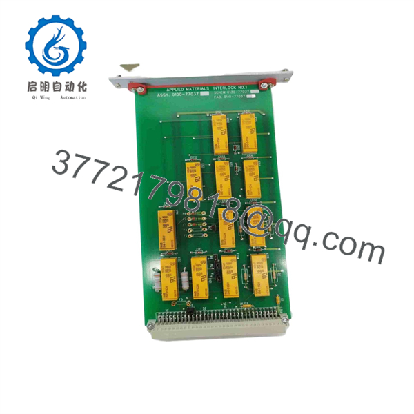
0100-77037
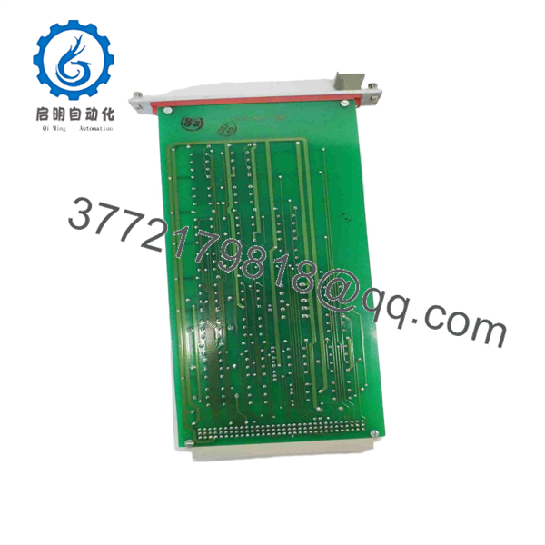
0100-77037
Frequently Asked Questions (FAQ)
Is this Applied Materials 0100-77037 board 100% New Surplus?
Yes. This board is 100% Genuine New Surplus. It has never been deployed in active cleanroom production and has been stored in anti-static, climate-controlled conditions. We adhere to a strict zero-tolerance policy regarding second-hand, pulled, or refurbished inventory.
Why pay a premium for New Surplus over a refurbished 0100-77037 module?
Refurbished semiconductor circuit boards frequently harbor latent ESD degradation, microscopic solder fractures, or dried electrolytic capacitors that trigger intermittent processing faults under thermal load. Spending 20–30% more for New Surplus guarantees factory-level integrity, full component lifespan, and protection against catastrophic tool crashes.
What is the OEM lifecycle status for the AMAT 0100-77037?
The 0100-77037 is a legacy, obsolete part with limited OEM factory availability. Fabs running mature 200mm or 300mm lines rely heavily on global New Surplus stock to support long-term tool retention and prevent supply chain disruptions.
Can I hot-swap this VME controller card during tool operation?
No. Hot-swapping 6U VME boards without dedicated hot-swap backplane logic causes power transients and pin arcing that can permanently destroy sensitive CMOS ICs across the entire card cage. Always disconnect main power prior to swapping hardware.
What warranty coverage comes with this part?
Unlike short 30-day warranties typical for used surplus parts, our New Surplus 0100-77037 module includes a full 1-year functional replacement warranty backed by static and power-up QC test verification logs.



