
 WhatsApp: +86 16626708626
 Email:
  Phone: +86 16626708626
Description
3. Key Technical Specifications
| Parameter | Specification / Value |
| Manufacturer | Applied Materials (AMAT) |
| Part Number | 0190-37684 |
| Component Type | Control & Communication I/O PCB Assembly |
| Input Supply Voltage | 24 VDC (±10% Tolerance) |
| Bus Architecture | Eurocard / Custom VMEbus Form Factor |
| Operating Temperature | 0°C to +55°C (+32°F to +131°F) |
| Storage Temperature | −40°C to +85°C (−40°F to +185°F) |
| Relative Humidity | 5% to 95% Non-condensing |
| Onboard Configuration | DIP switch addressable, onboard status LEDs |
| Packaging | Sealed Anti-Static Bag (ESD Shielded) |
4. Product Introduction & Supply Chain Strategy
This product is a Brand New Surplus unit. It is not used, not pulled from a decommissioned plant, and not refurbished. All modules undergo rigorous quality verification to ensure OEM-level reliability. The Applied Materials 0190-37684 PCB serves as a vital signal interface and process control board within AMAT semiconductor manufacturing toolsets, maintaining precise real-time communication between central processing units and chamber-level sensors.
Securing this module as New Surplus provides a crucial buffer stock against catastrophic tool down-time. Because OEM lead times for legacy wafer fabrication parts often exceed 16 to 24 weeks—or face outright end-of-life discontinuation—maintaining an on-site spare guarantees operational continuity. Refurbished boards present hidden failure risks, such as thermal fatigue on solder joints or aged capacitors. Investing in genuine New Surplus eliminates early failure risks while keeping your Total Cost of Ownership (TCO) lower than active OEM list pricing.
5. Installation & Configuration Guide
Stage 1: Pre-Installation (Prep & Safety)
- Enforce full Lock-Out/Tag-Out (LOTO) procedures on the host tool and drop all high-voltage rack power.
- Put on a grounded ESD wrist strap before opening the card cage enclosure.
- Take high-resolution photos of the existing board’s DIP switch banks, jumper positions, and cable routing for reference.
Stage 2: Removal
- Unplug all front-facing interface cables by pressing the connector side-latches; do not pull by the wiring harness.
- Unfasten the top and bottom card retaining screws on the faceplate.
- Grip the ejector handles firmly and swing them outward simultaneously to unseat the card from the backplane connectors without bending the rear pins.
Stage 3: Installation (Clone & Seat)
- Verify that the new 0190-37684 module matches the target slot pinout and board revision.
- Replicate all DIP switch positions and jumper blocks from the old board onto the new unit.
- Align the PCB edges with the card guide rails, push the module smoothly into the slot, and press the ejector handles inward until fully seated. Fasten the retaining screws.
Stage 4: Power-On & Testing
- Reconnect all front-panel interface cables according to your pre-installation photo.
- Apply 24 VDC logic power to the rack; confirm the power rail voltage reads between 23.8 VDC and 24.2 VDC using a calibrated multimeter.
- Observe the front LED indicators during the boot sequence: the Green RUN indicator should illuminate solid, and the Red ERR indicator must remain off.
1.Pre-Installation & Setup:Safety and configuration tracking.
Enforce LOTO procedures on the main tool rack. Wear a grounded wrist strap and photograph all DIP switches and jumper arrays on the original board before touching hardware.
2.Card Ejection:Protect backplane connections.
Unscrew top and bottom faceplate fasteners. Disengage the front ejector levers simultaneously to unseat the rear connectors straight back from the backplane without tilting.
3.Hardware Cloning & Insertion:Match switch states.
Mirror all DIP switch addresses onto the replacement 0190-37684 board. Slide the card evenly into the chassis rails until the ejector levers snap flush with the panel.
4.Validation & Boot Check:Confirm voltage levels.
Verify the 24 VDC bus logic rail shows proper supply range. Power on the card cage and ensure the RUN light illuminates green with zero active fault codes.
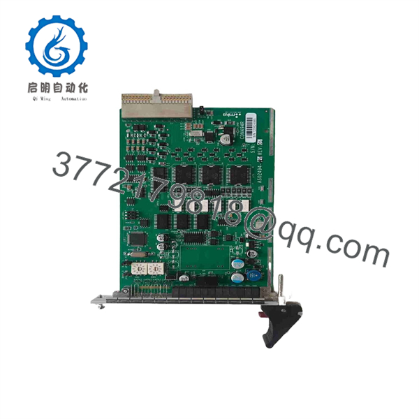
0190-37684
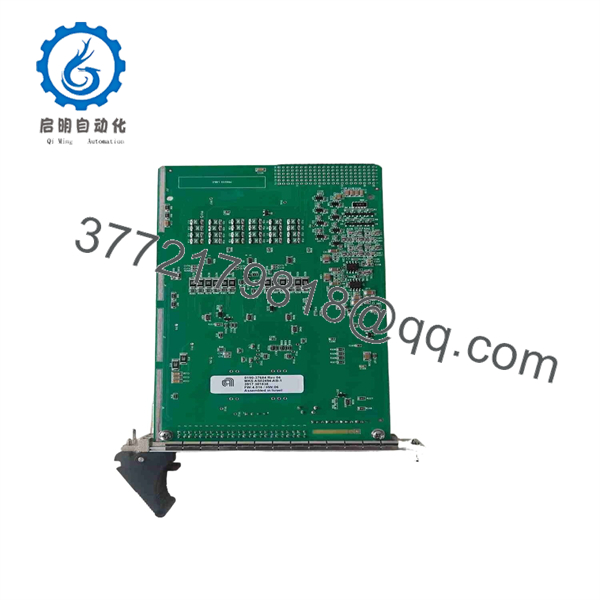
0190-37684
6. Firmware/Software Versions & Upgrade Notes
- Recommended Baseline Firmware: Board-level driver revisions must match the tool control platform release (compatible with V3.2x and V4.1x system architectures).
- Compatibility Matrix: Legacy hardware variants with earlier ASIC revisions cannot automatically downgrade from Firmware V4.xx to V2.xx without causing fieldbus timeout errors.
- Upgrade Warning: Do not attempt firmware flashing while the board is actively mounted in a live semiconductor production rack. Flashing failures can corrupt onboard EEPROM memory, requiring bench recovery. Always verify system software compatibility lists before swapping hardware revisions.
7. Frequently Asked Questions (FAQ)
Q: Is the Applied Materials 0190-37684 board brand new or refurbished?
A: This module is 100% Genuine New Surplus. It has never been deployed in an active production environment, contains zero re-soldered components, and shows no insertion wear on the gold backplane contacts.
Q: Why should I buy New Surplus instead of a cheaper refurbished option?
A: Refurbished boards often harbor invisible micro-cracks, thermally degraded capacitors, and worn relay contacts. In a semiconductor cleanroom, a single board failure can cause thousands of dollars per hour in unscheduled downtime. New Surplus delivers OEM-grade lifespan and reliability at a fraction of factory lead times.
Q: Is this board hot-swappable during tool operation?
A: No. Removing or inserting the 0190-37684 board while the backplane is energized can cause electrical arcs, corrupt onboard logic registers, and damage adjacent cards. Always drop rack power before installation.
Q: Do I need to program the module before installing it?
A: The board relies on hardware-level configuration via DIP switches and jumpers to set node addressing and communication protocols. Once these physical switches match your original board, the main tool controller automatically recognizes the hardware upon boot.
Q: What warranty coverage applies to this unit?
A: We back this 0190-37684 module with a comprehensive 1-year replacement warranty, giving you complete operational peace of mind compared to standard 30-day used-equipment guarantees.



