
 WhatsApp: +86 16626708626
 Email:
  Phone: +86 16626708626
Description
Key Technical Specifications
- Manufacturer: Applied Power Systems, Inc. (APS)
- Part Number: 100-1551-54
- Known Revisions in Market Listings: Rev. K and Rev. L
- Product Description: Gate digital integrated circuit board / gate-drive interface assembly
- Associated APS Assembly References: 100-1550 and 100-1551 appear on reseller listings; verify the complete board label before ordering
- Primary Application: Isolated gate control in industrial power-conversion equipment
- Publicly Listed Data Rate: 50 Mbps
- Publicly Listed Isolation Rating: 3,750 Vrms
- Publicly Listed Output Type: Totem-pole
- Weight Reported in One Listing: Approximately 170 g
- Compatible Equipment Context: Industrial drives, power conversion, marine power-management, and specialized control systems; exact application requires verification
- Power-Supply Requirement: Not publicly verified for 100-1551-54; do not apply the AP-1551 driver’s supply requirements to this board without confirmed documentation
- Connector Pinout and Gate-Drive Output Ratings: Not publicly verified; verify from the installed board, equipment schematic, or APS documentation before installation
Market information identifies APS 100-1551-54 as a gate digital integrated circuit board and associates it with the APS 100-1550 / 100-1551 board family. One reseller attributes 50 Mbps, 3,750 Vrms isolation, and a totem-pole output to the item, but those values should be confirmed from the physical board label or OEM documentation before publication as guaranteed specifications.
Product Introduction
The Applied Power Systems 100-1551-54 is a gate digital integrated circuit board used in specialized industrial power-electronics equipment. It is associated with APS 100-1550 and 100-1551 gate-control assemblies, where isolated signal handling and gate-drive timing are critical to the controlled switching of power semiconductors.
This board should be purchased as an exact replacement, with the revision confirmed before shipment. Match 100-1551-54, the installed Rev. K or Rev. L marking, connector layout, related 100-1550 assembly reference, and equipment wiring before installation. Do not substitute by appearance; a gate-drive board with different timing, isolation, or output behavior can damage the IGBT power stage.
Troubleshooting Quick Reference
| Symptom | Possible Cause | Relevance to This Part | Quick Check Method | Recommendation |
|---|---|---|---|---|
| Power converter will not start | Missing auxiliary supply, open fuse, controller inhibit, interlock active, failed gate-drive board, or failed IGBT stage | ✅ Medium to High | Apply lockout/tagout and wait for DC-link capacitors to discharge. Verify the DC bus is at a safe level using a properly rated meter. Check the control supply and board-side supply rails against the equipment schematic. | Start with incoming power, auxiliary supplies, fuses, and interlocks. Do not replace the board before confirming that the converter has valid control power. |
| Converter trips immediately on enable | Shorted IGBT, shorted gate-emitter path, failed driver output, incorrect gate wiring, desaturation fault, or controller timing issue | ✅ High | With power removed and capacitors discharged, test the power stage using the OEM-approved diode-check procedure. Check for an abnormally low resistance between gate and emitter on the connected device. Review trip codes before clearing them. | Inspect the IGBT module and connected gate harness before installing a replacement board. A shorted IGBT can destroy a new driver board at first enable. |
| Repeated overcurrent or desaturation trip | Failed IGBT, gate-drive loss, poor gate connection, load short, current-sensor error, or incorrect dead time | ✅ High | Capture the exact trip code and operating condition. Inspect gate-emitter harness continuity and connector seating with power removed. Use an isolated oscilloscope only if qualified procedures and appropriate probes are available. | Do not bypass protection circuits. Determine whether the trip originates in the power stage, load, current sensing, or gate-drive path. |
| One inverter leg fails while other phases operate | One gate channel fault, failed IGBT, damaged gate harness, power-module defect, or controller output failure | ✅ High | Compare the suspect phase with a known-good phase using the equipment schematic. Check harness continuity, connector pins, and IGBT diode behavior. Verify controller command signals only with properly isolated instrumentation. | Replace the board only after the fault follows the specific driver channel and external wiring or IGBT failures are excluded. |
| Board operates cold but fails after warming up | Cracked solder joint, thermal stress, weak auxiliary supply, marginal optocoupler, or deteriorated component | ✅ Medium | Review the fault’s time-to-failure. Inspect for discoloration, cracked solder joints, and loose connectors. Measure the documented auxiliary supply under load, not only at idle. | Correct cabinet cooling and supply problems first. If the fault follows the board during controlled substitution, replace it. |
| No gate signal at the power device | Controller inhibit, missing logic supply, broken harness, failed driver output, shutdown input active, or failed IGBT gate path | ✅ Medium to High | Confirm the controller enable condition and board supply rails. Check the gate harness end-to-end with power removed. Use a differential probe rated for the circuit if waveform testing is authorized. | Verify the inhibit chain and harness before condemning the PCB. Never connect a grounded oscilloscope probe to a floating high-side gate circuit. |
| New board fails immediately after installation | Existing IGBT short, wiring error, wrong board revision, incorrect connector insertion, ESD damage, or incorrect supply rail | ✅ High | Remove power immediately. Inspect the IGBT module, gate wiring, connector keying, and supply rails. Compare the old and replacement board labels, revision marks, and component placement. | Correct the root cause before another replacement. Repeatedly installing boards into a shorted power stage is an expensive way to find a failed IGBT. |
| Visible scorching, odor, or damaged components | Overvoltage, power-stage failure, contamination, failed output device, or internal board fault | ✅ High | Do not reapply power. Photograph both sides of the board. Inspect the connected IGBT and gate harness for shorts, damaged insulation, and incorrect grounding. | Keep the failed board for analysis. Replace only after the external cause is identified and corrected. |
❗ High-voltage warning: Treat every power converter as energized until you verify the DC link is discharged with a correctly rated meter. Capacitors can retain hazardous voltage after the incoming supply is isolated.
❗ IGBT warning: Do not install a replacement gate board until you test the connected IGBT power stage. I have seen a technician fit a new driver card into a converter with a shorted IGBT; the replacement failed immediately on the first enable command. Check the semiconductor module first.
❗ Revision warning: Rev. K and Rev. L are not automatically interchangeable. Photograph the entire original board, including every label, connector, jumper, and component-side marking before removal. Confirm the exact revision with the supplier.
❗ Instrumentation warning: Do not use a standard earth-referenced oscilloscope probe on a floating high-side gate circuit. Use an approved differential probe and follow the equipment manufacturer’s test procedure.
If the fault remains unclear, provide technical support with the full board label, revision marking, equipment model, converter fault code, photos of the gate harness and power module, measured auxiliary supply values, and any approved scope captures. Keep these checks in mind and you will save yourself 90% of typical rework time.
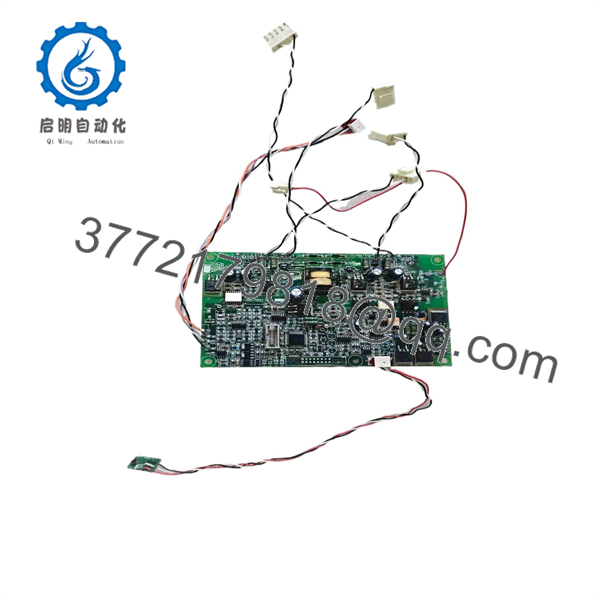
100-1551-54
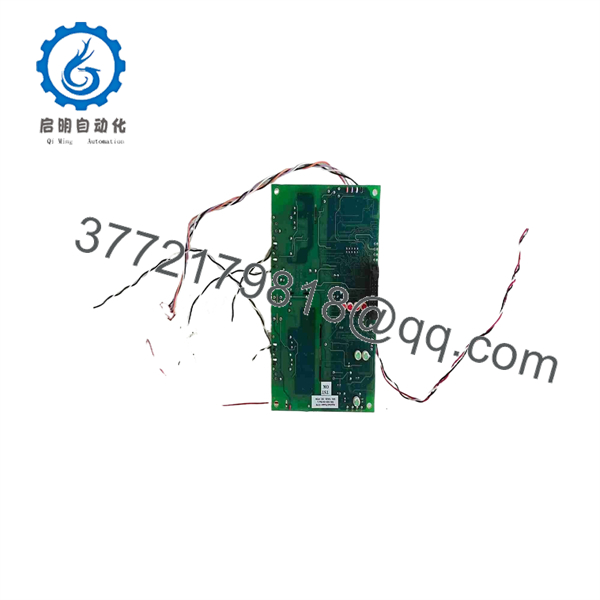
100-1551-54
Frequently Asked Questions (FAQ)
What is APS 100-1551-54?
APS 100-1551-54 is a gate digital integrated circuit board associated with Applied Power Systems power-electronics hardware. Market listings link it to the APS 100-1550 and 100-1551 board family, where the board serves a gate-control or isolated drive-interface role for industrial power-conversion equipment.
Is 100-1551-54 an IGBT driver board?
It is commonly described as a gate digital board or gate-control interface, and it is associated with APS IGBT gate-drive equipment. However, confirm the exact function from your board label and equipment schematic before ordering. APS also publishes a separate AP-1551 half-bridge IGBT gate-drive board, but that product should not be assumed identical to 100-1551-54.
Are Rev. K and Rev. L interchangeable?
Do not assume they are interchangeable. Listings show both Rev. K and Rev. L markings for 100-1551-54-related assemblies, but public sources do not establish their electrical compatibility. Revision changes can alter gate timing, protection behavior, connector assignments, firmware, or component ratings. Match the full original label and revision before issuing a purchase order.
Can I hot-swap this board?
No. Treat this as a non-hot-swappable power-electronics board. Gate-drive circuits can connect to hazardous DC-link systems, isolated supplies, IGBT gates, and sensitive logic signals. Shut down the converter, follow lockout/tagout procedures, verify capacitor discharge, use ESD protection, and wait for the manufacturer-specified discharge time before removal.
Do I need to replace the IGBT module with the board?
Not automatically. Test the IGBT module, gate-emitter circuit, output load, and gate harness before ordering a board. If the IGBT is shorted, installing a replacement driver board before replacing the semiconductor can destroy the new board. If the IGBT tests correctly and the fault follows the driver board during a controlled substitution, the board becomes the likely suspect.
Why is a New Surplus 100-1551-54 less expensive than an OEM order?
New Surplus stock generally comes from unused project inventory, excess spares, equipment decommissioning, distributor liquidation, or long-term MRO stores. It can be original material but may be outside the active OEM supply chain. Because this is likely a legacy part, stock can be limited and revision-specific.
Request actual photographs of the board, all labels, the exact revision, connector condition, packaging, test documentation, stock quantity, shipping lead time, and written warranty before payment. Do not accept a generic stock image for an IGBT gate-control board.
How should a supplier test an APS 100-1551-54 board?
The supplier should first inspect source traceability, revision labels, component condition, connectors, solder joints, traces, corrosion, rework evidence, and ESD handling. They should confirm that the board is not merely visually clean but electrically suitable for use.
Functional testing should use a documented APS-compatible test fixture or the correct power-converter control environment. The test should verify low-voltage power-up behavior, logic isolation where applicable, command-response behavior, output-channel operation, protection/inhibit behavior, and stable operation under a controlled load. Test personnel should use isolated, correctly rated equipment because gate-driver circuits can involve hazardous voltage.
Final QC should include an inspector sign-off, ESD shielding bag, protective cushioning, rigid packaging, and a dated QC label. Request a written test report, actual board photographs, and test video when available.



