
 WhatsApp: +86 16626708626
 Email:
  Phone: +86 16626708626
Description
Key Technical Specifications
| Parameter | Value |
|---|---|
| Model | ASM 4552200 |
| Brand | ASM |
| Product Type | Industrial position / proximity sensor module |
| Operating Voltage | 10–30 VDC* |
| Output Type | PNP* |
| Sensing Technology | Inductive proximity sensing* |
| Switching Frequency | Up to 500 Hz* |
| Response Time | Approximately 0.5 ms* |
| Protection Rating | IP67* |
| Operating Temperature | Approximately −25 to +70°C* |
| Mounting | Flange mount* |
| Cable Length | Approximately 2 m* |
*These specifications appear in third-party listings and should not be treated as confirmed OEM specifications without checking the nameplate, equipment manual, or original ASM documentation. One source instead lists a wider −40 to +85°C range and different electrical details, so the exact revision must be verified before installation.
Product Introduction
The ASM 4552200 is listed as an industrial position/proximity sensing component used for object detection and position feedback in automated machinery. Available supplier documentation associates the part with inductive sensing, PNP output, 10–30 VDC operation, and IP67 protection.
For replacement work, the exact electrical variant matters more than the generic part-number description. Verify the nameplate, connector arrangement, sensing distance, output logic, and supply voltage against the installed unit before ordering or commissioning.
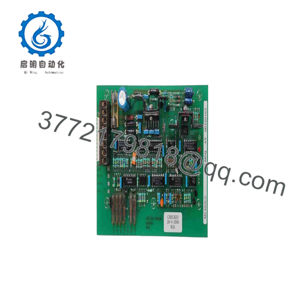
4552200
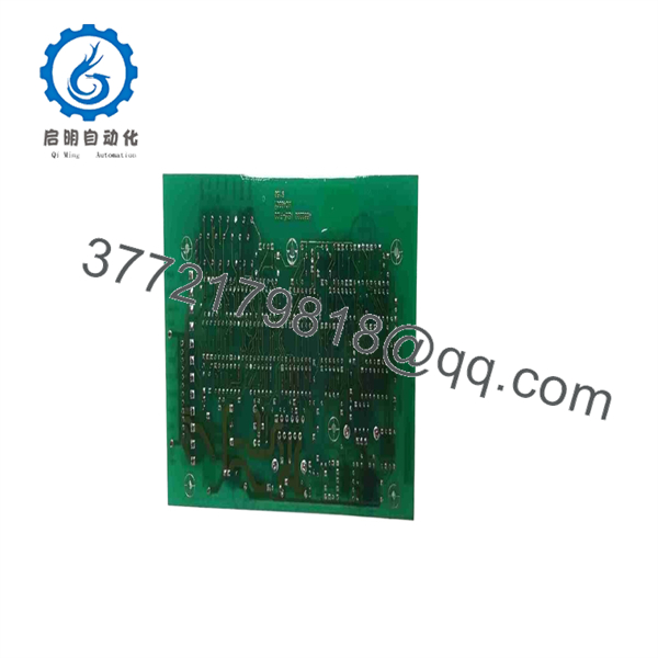
4552200
Installation & Configuration Guide
Stage 1: Pre-Installation Preparation — Approx. 10 minutes
⚠️ Safety First
- Notify operations and confirm the equipment can be stopped safely.
- Place the machine in its defined safe state.
- Apply the site’s lockout/tagout procedure before disconnecting the sensor.
- Wait at least 5 minutes where the machine manufacturer specifies capacitor discharge time.
- Confirm the relevant supply is de-energized with a properly rated multimeter.
Tools Required
- ESD wrist strap
- PH1 screwdriver or the correct driver for the installed hardware
- Digital multimeter
- Wire labels
- Smartphone or camera for configuration photos
Data Backup
- Record the existing sensor model and complete nameplate information.
- Photograph the connector and cable routing before removal.
- Record PLC/HMI channel assignment.
- Document supply voltage and output wiring.
- If the sensor connects through an interface module, record the terminal number and signal type.
Do not assume that every ASM 4552200 installation uses the same connector or output configuration. Public listings disagree on several specifications.
Stage 2: Removing the Old Module — Approx. 5 minutes
- Remove the protective cover or access panel if fitted.
- Label every wire before disconnecting it.
- Photograph the terminal arrangement from several angles.
- Disconnect the wiring without pulling on the cable.
- Release the mounting hardware or retaining mechanism.
- Remove the sensor straight from its mounting position.
- Inspect the mounting surface for contamination, mechanical damage, or excessive vibration.
- Inspect the connector for corrosion, bent contacts, or damaged seals.
⚠️ Keep the original sensor until the replacement has passed the complete functional test. The old unit is your best reference for connector orientation, sensing position, cable routing, and mechanical alignment.
Stage 3: Installing the New Module — Approx. 5–10 minutes
- Wear a grounded ESD wrist strap when handling the electrical connector or exposed electronics.
- Verify that the replacement is marked ASM 4552200 and compare the complete nameplate against the removed unit.
- Confirm the supply voltage before applying power.
- Compare the connector pinout with the machine wiring diagram.
- Do not wire from memory.
- Install the sensor in the original mounting position.
- Restore the original mechanical alignment and sensing gap.
- Reconnect the wiring according to the documented terminal assignment.
- Secure the connector and cable so vibration cannot transfer mechanical load into the connector.
- Confirm that any IP-rated sealing components are correctly seated.
Self-Checklist
- Exact part number verified
- Supply voltage verified
- Connector/pinout verified
- Output type verified
- Mechanical position matched
- Sensing gap verified
- Wiring secured
- Cable strain relief secured
Stage 4: Power-On & Testing — Approx. 10 minutes
Pre-Power Check
- Check the supply rail with the multimeter.
- Verify there is no short circuit between supply and common.
- Confirm polarity.
- Confirm the PLC input channel corresponds to the documented sensor output.
Power-On Steps
- Energize the control circuit.
- Observe the sensor and PLC input status.
- Place the target object in the normal sensing position.
- Confirm that the PLC input changes state.
- Move the target through the expected operating range.
- Verify repeatable detection.
- Check the HMI or diagnostic software for input faults.
- Run the machine through a controlled dry cycle.
- Perform a production-speed test only after the basic signal test passes.
⚠️ If the PLC input remains permanently ON or OFF, do not immediately assume the sensor is defective. Check PNP/NPN compatibility, common reference wiring, supply polarity, sensor gap, and the PLC input configuration first.
Technical Replacement Pitfalls
❗ Output-type mismatch: A replacement listed as PNP cannot automatically replace an NPN installation. Check the actual PLC input circuit before connecting it.
❗ Supply-voltage mismatch: Never apply an assumed voltage merely because another sensor in the same machine uses it. Confirm the voltage on the original nameplate or machine documentation.
❗ Mechanical alignment: With position sensors, a physically correct installation can still fail if the sensing distance or target geometry changes.
❗ Connector assumptions: Similar-looking industrial sensor connectors can have different pin assignments. Verify the drawing before energizing the circuit.
❗ ESD: Use a grounded wrist strap when handling exposed electronics. A sensor that fails immediately after replacement may have been damaged during installation rather than during operation.
❗ Specification uncertainty: Public listings for ASM 4552200 contain conflicting values for temperature range, sensing distance, and electrical characteristics. For a production-line replacement, the OEM nameplate and machine-specific documentation take priority over reseller specifications.
Frequently Asked Questions (FAQ)
Q1. Can the ASM 4552200 be hot-swapped?
Do not assume it can. The available documentation does not establish a hot-swap rating for ASM 4552200. Unless the machine manufacturer explicitly permits live replacement, isolate the relevant power circuit before disconnecting the sensor.
Q2. Is ASM 4552200 an obsolete model?
The available public sources do not establish a reliable OEM lifecycle status. Treat it as a potentially legacy or application-specific component until ASM documentation confirms current production status. Availability may therefore depend on surplus or remaining industrial inventory.
Q3. Is the ASM 4552200 genuinely new?
That depends on the individual unit being supplied. A part number alone does not establish condition. For procurement, specify Factory Sealed, New Original/New Surplus, or Refurbished and Tested and request photographs of the actual nameplate and packaging.
Q4. Can I use another proximity sensor as a direct replacement?
Not without checking the complete interface. Compare supply voltage, PNP/NPN output, normally-open/normally-closed logic, sensing distance, connector pinout, mounting dimensions, cable length, and environmental rating. A sensor that physically fits can still be electrically incompatible.
Q5. Will replacing the sensor erase my PLC program?
Normally, replacing a field sensor does not erase PLC logic. The PLC program resides in the controller’s memory, not in the sensor. However, the machine may generate an I/O fault if the replacement produces a different signal type or electrical state.
Q6. Why do published specifications for ASM 4552200 differ?
This is a legitimate concern. Several reseller pages identify ASM 4552200 as a Pepperl+Fuchs/ASM position or proximity component but publish different temperature, sensing-distance, and electrical values. I would not release a purchase order based solely on those listings. Match the replacement against the installed unit’s nameplate and machine documentation first.
Q7. What should I provide when requesting a replacement?
Provide the complete ASM 4552200 marking, photographs of the nameplate and connector, the machine model, supply voltage, PLC input type, and the original sensor’s mounting arrangement. Those details are far more useful than the part number alone when confirming compatibility.



