
 WhatsApp: +86 16626708626
 Email:
  Phone: +86 16626708626
Description
Key Technical Specifications
- Manufacturer: Autronica
- Board model: KRH-1
- Part number: 7225-032.0001
- Board category: Printed circuit board card
- Associated system: KR-20 marine alarm and control equipment
- Reported unit position: Unit-7
- Primary function: System-dependent signal processing or alarm-control interface
- Installation format: Internal plug-in PCB assembly
- Application environment: Marine automation and alarm systems
- Electrical ratings: Not verified in the public sources reviewed
- Connector pinout: Must be confirmed from the applicable KR-20 documentation
- Firmware or board revision: Confirm from the physical label before ordering
- Approximate listed weight: 70 g
- Service status: Legacy/limited-stock component
- Certification requirements: Verify vessel and classification requirements before installation
Public listings identify Autronica part number 7225-032.0001 as a KRH-1 printed circuit board card. Other supplier listings associate the board with the KR-20 system and Unit-7 designation, but the reviewed public sources do not provide a complete electrical datasheet or verified terminal specification.
Product Introduction
The Autronica KRH-1, part number 7225-032.0001, is a system-specific printed circuit board used in legacy KR-20 marine alarm and control equipment. It is intended for replacement work where the installed board label, connector arrangement, and system documentation match.
Publicly available data confirms the board identity but does not establish complete voltage, I/O, pinout, or environmental specifications. Treat this as a controlled marine-electronics spare: verify the panel assembly, Unit-7 position, board revision, connector keying, and classification requirements before installation.
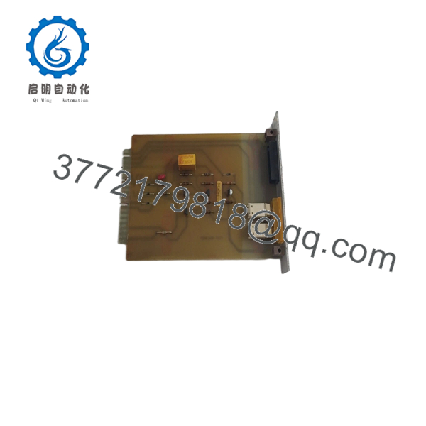
7225-032.0001
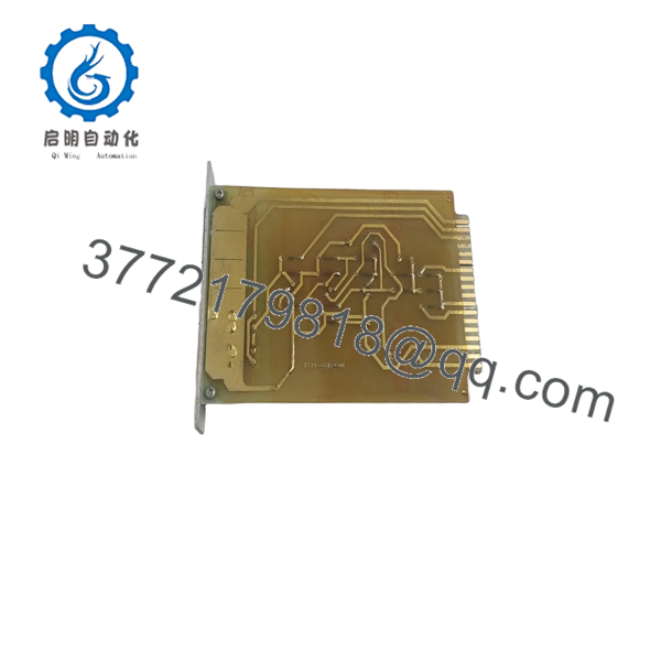
7225-032.0001
Troubleshooting Quick Reference
| Symptom | Possible Cause | Relevance to This Part | Quick Check Method | Recommendation |
|---|---|---|---|---|
| Alarm panel or controller does not power up | Main supply, fuse, power board, or shorted module | ❌ Low | Measure the system’s specified DC supply at the panel input and inspect power indicators | Check system power before replacing the KRH-1 |
| Unit-7 is not recognized | Loose connector, incorrect board position, damaged edge contacts, or board fault | ✅ High | Compare the board position with the system drawing, then reseat it with power isolated | Inspect contacts and seating before replacing the PCB |
| Multiple alarm channels fail together | Common supply, bus, backplane, or controller fault | ❌ Low to medium | Check whether failures are limited to Unit-7 or affect adjacent units | Diagnose the shared system path before condemning this board |
| One alarm input is permanently active | Field wiring short, sensor fault, incorrect common, or input-channel failure | ✅ Medium | Isolate the field wire and measure the input at the board terminal or connector using the approved procedure | Separate field-circuit faults from board faults before replacement |
| One alarm channel remains inactive | Open field circuit, failed sensor, connector issue, or PCB input fault | ✅ Medium | Test with an approved simulator or known-good field signal and compare with another channel | Replace the board only if the test signal reaches the correct input and is not detected |
| Intermittent alarms occur during vibration | Loose connector, cracked solder joint, corrosion, or unstable field wiring | ✅ Medium | Inspect under magnification and perform a controlled vibration or continuity check with power isolated | Correct mechanical or wiring faults; do not install an untested spare |
| System resets when an alarm is triggered | Supply droop, overload, short circuit, or board failure | ✅ Medium | Monitor the system supply during an approved alarm test and inspect fuses and wiring | Correct supply capacity and wiring before replacing the PCB |
| Replacement board does not operate | Wrong revision, incompatible system, or incorrect board location | ✅ High | Compare the entire part number, board marking, connector layout, and Unit-7 reference | Stop installation and obtain documentation or supplier confirmation |
| Fault follows the board after swapping with an approved spare | Internal PCB failure | ✅ High | Record the original fault, install a known-good compatible card, and repeat the approved test | Replace with an exact, tested equivalent and document the result |
| Visible corrosion or burnt components | Moisture ingress, salt contamination, overvoltage, or short circuit | ✅ High | Photograph damage, inspect surrounding connectors, and test for contamination before energizing | Quarantine the board and identify the failure cause before fitting another unit |
Critical warning: This PCB may be part of a marine alarm or safety-related control system. Do not bypass alarms or return the vessel system to service based only on a successful power-up. If the fault remains unclear, contact technical support with the complete system model, board photographs, Unit-7 location, connector images, alarm log, measured supply voltages, and test records.
Frequently Asked Questions (FAQ)
What is Autronica 7225-032.0001?
It is identified by public supplier listings as the Autronica KRH-1 printed circuit board card. Listings also associate it with KR-20 marine alarm and control equipment.
Is this board a general-purpose PLC I/O module?
No. The KRH-1 should be treated as a system-specific Autronica PCB, not as a universal PLC input or output card. Its exact function depends on the KR-20 assembly, board position, wiring, and system revision.
What are the electrical specifications and pinout?
The public sources reviewed do not provide a verified electrical datasheet, terminal map, input thresholds, output ratings, or supply requirements. Obtain the correct KR-20 service documentation or a confirmed supplier test sheet before connecting power or field wiring.
Can I substitute another Autronica board with a similar 7225 part number?
Do not substitute by appearance or partial part number. Compare the complete 7225-032.0001 number, marking, revision, connector layout, mounting position, and system documentation. A different 7225 board may perform a different function.
Can I replace the while the system is energized?
Do not hot-swap this PCB. Isolate power using the approved marine maintenance procedure, verify the system is in the required maintenance state, and confirm temporary alarm coverage before removal.
Is the 7225-032.0001 obsolete?
It appears to be a legacy or limited-stock marine electronics component. Supplier listings show used and surplus availability, but the reviewed sources do not establish a current production status. Request the exact condition, board revision, photographs, warranty, and test evidence for the offered unit.
Why is a used PCB cheaper than a factory replacement?
Legacy marine PCBs may come from removed equipment, surplus stock, or refurbished inventory. The listing should clearly state New Original, New Surplus, Used, or Refurbished (tested). For vessel service, request traceability, insulation and continuity test records where applicable, connector inspection results, and written warranty terms before purchase.



