
 WhatsApp: +86 16626708626
 Email:
  Phone: +86 16626708626
Description
Key Technical Specifications
| Parameter | Value |
|---|---|
| Manufacturer | AUTRONICA Fire and Security |
| Model | BSA200A |
| Board designation | BSA-200A |
| Product category | Main circuit board |
| System | Autroprime Interactive Fire Detection System |
| System version | Autroprime Version 2 and later |
| Hardware revision | BSA-200A; exact revision must be verified from board label |
| USB interface | 1 USB connector on BSA-200A |
| Detection-loop technology | Autronica AL_Com Loop Technology |
| Standard loop capacity | Autroprime panel prepared for 2 detection loops |
| Maximum loop capacity | Up to 4 with BSD-200A/PACK |
| Commonly listed part number | 9212-385.1001; verify against the installed board before ordering |
Autronica documentation identifies BSA-200A as the main circuit board used in Autroprime Version 2 and later systems. The documentation also distinguishes it from the older BSA-200 board: BSA-200 has two USB connectors, while BSA-200A has one.
Autronica states that BSA-200A hardware revision 8 and BSD-200A hardware revision 5 require Autroprime System Software version 2.0 or later. This makes the exact hardware revision and installed software version important procurement checks, not just the BSA200A model designation.
Product Introduction
The AUTRONICA BSA200A is the main circuit board used in the Autroprime Interactive Fire Detection System. It provides the central hardware platform for the fire alarm control panel and interfaces with the system’s detection-loop and panel-bus architecture. Autronica documentation identifies as the later main-board revision used with Autroprime Version 2 and subsequent configurations.
For replacement work, the board revision matters. Do not treat BSA200A as interchangeable with every BSA-200 or later BSA-200B assembly without checking the complete panel configuration, software version, power-supply arrangement, and installed options. Autronica specifically documents compatibility relationships between hardware and Autroprime system software.
Installation & Configuration Guide
Stage 1: Pre-Installation Preparation — Allow 10–15 Minutes
⚠️ Safety First: The BSA200A belongs to a fire detection and alarm system. Put the affected fire protection system into an approved maintenance state and notify the responsible operations/fire-safety personnel before removing the board.
- Record the complete board identification. Photograph the BSA200A label, hardware revision, serial information, connectors, and any visible configuration settings.
- Record the installed Autroprime software version. This is particularly important because documented hardware revisions have specific software requirements.
- Export or otherwise preserve the current system configuration using the approved Autronica service procedure.
- Photograph every connector before disconnection.
- Label field and auxiliary wiring if there is any possibility of confusion during reassembly.
- Prepare an ESD wrist strap, suitable screwdriver, multimeter, labels, and a phone or camera.
- Do not assume the replacement board is a drop-in substitute solely because it is marked . Verify the hardware revision and part number.
Stage 2: Removing the Existing Board — Allow 5–10 Minutes
- Place the fire alarm system into the appropriate authorized maintenance condition.
- Isolate power according to the Autroprime installation procedure.
- Do not work on the board while energized unless the OEM procedure explicitly permits the operation.
- Allow stored energy to discharge before handling the PCB.
- Photograph the original installation from several angles.
- Disconnect connectors carefully. Do not pull on individual wires.
- Remove the board’s mechanical retaining hardware.
- Lift the PCB out without contacting exposed circuitry or connector pins.
- Inspect the panel wiring and connectors for corrosion, loose terminals, contamination, or mechanical damage.
- Keep the original until commissioning is complete.
Stage 3: Installing the Replacement — Allow 5–10 Minutes
- Put on a grounded ESD wrist strap and work on an appropriate ESD-safe surface.
- Verify the replacement board identification against the removed board.
- Check the PCB for shipping damage, bent connector pins, contamination, or evidence of rework.
- Confirm the hardware revision before installation.
- Position the board correctly in the panel.
- Secure the PCB using the original mounting hardware.
- Reconnect each connector according to the photographs and Autronica wiring documentation.
- Check connector seating mechanically before applying power.
- Verify that no cable is trapped underneath the PCB or against a heatsink or sharp chassis edge.
- Inspect the board once more before restoring power.
Stage 4: Power-On & Commissioning — Allow 10–20 Minutes
- Perform a final wiring and polarity inspection before energizing the panel.
- Restore the approved power configuration.
- Observe the board and panel status indicators during startup.
- Verify that the Autroprime system completes its normal boot sequence.
- Confirm the installed software version.
- Check that the hardware revision is compatible with the installed software. Autronica documentation specifies System Software 2.0 or later for hardware revision 8.
- Verify detection-loop communication.
- Verify panel-bus communication where applicable.
- Test the operator panel and relevant alarm indications.
- Perform the required fire detection, alarm, fault, and output tests under the site’s approved commissioning procedure.
- Record the replacement board’s identification and software/hardware versions in the maintenance record.
⚠️ Commissioning Warning: Do not return a fire alarm system to normal service merely because the panel powers up. Confirm detection loops, alarm outputs, faults, panel communication, and all affected interfaces before closing the maintenance activity.
Compatibility checkpoint: Autroprime uses Autronica’s AL_Com Loop Technology for detection-loop communication. The standard panel is prepared for two loops and can be expanded to four with BSD-200A/PACK; therefore, replacement-board verification should consider the complete panel configuration rather than the PCB alone.
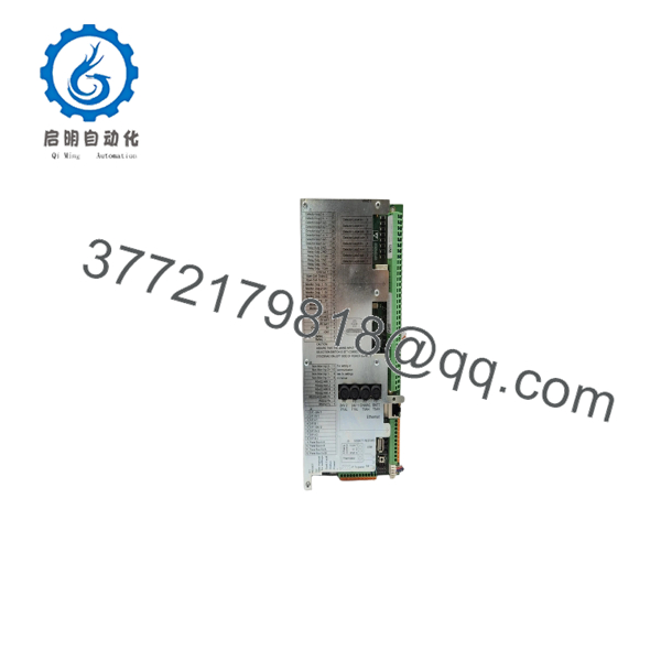
BSA200A
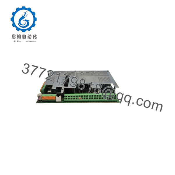
BSA200A
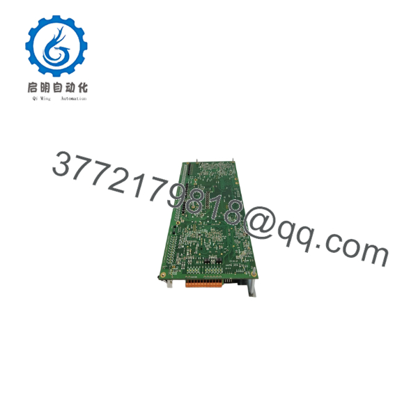
BSA200A
Frequently Asked Questions (FAQ)
Can the AUTRONICA be hot-swapped?
Do not assume that it can. The is the main circuit board of the Autroprime fire alarm control panel, so replacement should be performed with the panel in an authorized maintenance condition and power isolated according to the applicable Autronica procedure. A live-board replacement could create faults or compromise fire protection functions.
Is the same as the older BSA-200?
No. Autronica documentation identifies BSA-200 and as different main-board revisions. One easy physical distinction is the USB interface: the older BSA-200 has two USB connectors, while has one. The version was produced from 2012 onward according to Autronica’s software-upgrade documentation.
What Autroprime software version is required?
The exact requirement depends on the hardware revision. Autronica states that hardware revision 8 requires Autroprime System Software version 2.0 or later. Do not order a replacement board without recording the hardware revision and existing software version.
Is still available as a new original part?
Availability and condition vary because this is a legacy Autroprime main-board assembly. Current secondary-market listings identify PCB assemblies, including listings for 9212-385.1001, but those listings should not be treated as proof of factory-new OEM condition. One current listing identifies a PCB as used, while another listing identifies the same part-number family with a different revision.
For procurement, request photographs of the actual board, the PCB revision, serial information, and packaging condition before purchase.
What part number should I use when ordering?
is the model designation, but the complete board identification should be checked before purchase. Secondary-market documentation commonly associates with 9212-385.1001, while other listings identify Autronica main-board assemblies using numbers such as 7212-385.0009. These should not automatically be treated as interchangeable.
Can support four detection loops?
The Autroprime panel is normally prepared for two detection loops. Autronica documents expansion to a maximum of four detection loops using the BSD-200A/PACK loop extension package. The maritime variant is prepared for four loops.
Will replacing the preserve my existing programming?
Do not assume it will. Treat the replacement as a controlled fire-alarm-system service activity. Preserve the existing configuration before removing the board and verify the configuration after installation using the approved Autronica service procedure. Hardware revision, system software, panel configuration, loop configuration, and installed options all need to be checked before returning the system to service.



