
 WhatsApp: +86 16626708626
 Email:
  Phone: +86 16626708626
Description
Key Technical Specifications
| Parameter | Value |
|---|---|
| Manufacturer | AUTRONICA Fire and Security |
| Model | BSL-100 |
| Product designation | BSL-100 |
| Product category | Fire detection system module |
| Application | Autronica fire alarm and detection systems |
| System compatibility | Model- and revision-dependent |
| Installation | Autronica control-panel/system assembly |
| Communication/interface | System-specific; verify OEM documentation |
| Power requirements | Verify against the installed system |
| Environmental rating | Verify against the applicable system documentation |
| Firmware/configuration | System-dependent |
| Replacement status | Verify current OEM/legacy status before procurement |
Procurement note: The available source material establishes the required writing framework but does not provide enough BSL-100-specific electrical, dimensional, environmental, or communication specifications to state those values reliably. Those parameters should be confirmed from the exact OEM documentation or the nameplate on the installed module rather than guessed.
Product Introduction
The AUTRONICA BSL-100 is a module associated with Autronica fire detection equipment. Its exact system role and electrical characteristics should be matched against the installed panel, system generation, and board revision before replacement.
For maintenance procurement, the model number alone is not enough to establish interchangeability. Confirm the complete identification on the existing BSL-100, including any revision or secondary part number, and compare the connector arrangement and system documentation before installation.
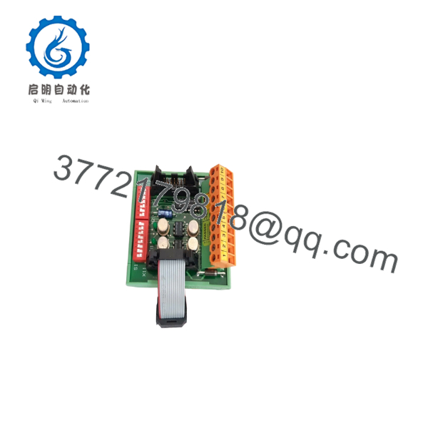
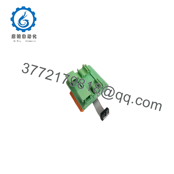
BSL-100
Installation & Configuration Guide
Stage 1: Pre-Installation Preparation — Allow 10–15 Minutes
⚠️ Safety First: Place the affected fire detection system into its approved maintenance condition and notify the responsible operations/fire-safety personnel before beginning work.
Tools Required:
- ESD wrist strap
- Appropriate screwdriver
- Digital multimeter
- Wire labels
- Smartphone or camera
Preparation:
- Record the complete BSL-100 model and any revision/part number.
- Photograph the installed module and every connector.
- Record the existing panel/system configuration.
- Identify the exact Autronica panel in which the is installed.
- Confirm the replacement has the same physical and electrical identification.
- Follow the site’s lockout/tagout procedure before accessing energized circuitry.
Stage 2: Removing the Old Module — Allow 5–10 Minutes
- Place the fire alarm system in the approved maintenance state.
- Isolate power according to the applicable Autronica installation procedure.
- Verify the absence of hazardous voltage where appropriate.
- Label connected wiring before removal.
- Disconnect connectors without pulling on individual conductors.
- Release the module’s mechanical retaining hardware.
- Remove the straight from its mounting position.
- Inspect connectors, terminals, and the mating assembly for contamination or physical damage.
- Keep the original module until the replacement has passed commissioning.
Stage 3: Installing the Replacement — Allow 5–10 Minutes
- Put on an ESD wrist strap.
- Verify the exact identification before installation.
- Compare connector positions with the original module.
- Check the replacement PCB for bent pins, corrosion, or shipping damage.
- Install the module in the correct orientation.
- Secure the module mechanically.
- Reconnect all wiring using the photographs taken during removal.
- Check connector seating and cable routing.
- Confirm that no wiring is trapped or under mechanical stress.
Self-Checklist:
- Exact model/revision verified
- Connector positions match
- Wiring correctly identified
- Module mechanically secured
- ESD precautions maintained
Stage 4: Power-On & Testing — Allow 10–20 Minutes
- Perform a final wiring inspection before restoring power.
- Restore system power according to the approved procedure.
- Observe the control panel during startup.
- Check for module or system fault indications.
- Verify communication with the affected subsystem.
- Test the applicable detection and alarm functions.
- Confirm that no unexpected fault remains.
- Record the replacement module’s identification and system status.
⚠️ Commissioning Warning: A module that powers up without an obvious fault is not necessarily proven functional. Complete the applicable fire detection, alarm, fault, and interface tests before returning the system to normal service.
Frequently Asked Questions (FAQ)
Can the AUTRONICA be hot-swapped?
Do not assume that it can. Unless the specific Autronica system documentation explicitly permits live replacement, isolate the relevant power and follow the approved maintenance procedure. Fire alarm equipment should not be treated like a generic plug-in I/O module.
Is compatible with every Autronica fire alarm panel?
No. The model designation alone does not establish universal compatibility. Check the exact control panel, system generation, hardware revision, connector arrangement, and OEM documentation before ordering.
Is the obsolete?
The available source material does not establish a definitive current lifecycle status for . Treat it as a potentially legacy component until current OEM availability is confirmed.
Can I use a used as a replacement?
Potentially, but condition matters. A used module should be visually inspected and electrically/functionally tested before being placed into a fire protection system. Ask the supplier for the actual module photographs, identification label, test results, and return/warranty terms.
Why is the supplier price lower than the OEM list price?
For legacy industrial automation and fire detection components, lower pricing can reflect surplus inventory, discontinued production, used stock, or refurbished inventory. It does not by itself establish equivalence to factory-new OEM stock. Confirm the stated condition before purchasing.
What information should I send before ordering a ?
Send a clear photograph of the existing module’s full label, including the model, revision, serial/part number, and connector area. Also provide the Autronica panel model if available. That information is far more useful for compatibility verification than the model number alone.



