
 WhatsApp: +86 16626708626
 Email:
  Phone: +86 16626708626
Description
Key Technical Specifications
| Parameter | Specification |
| Manufacturer | Autronica Fire and Security |
| Model / Part Number | BSL-111A |
| Assembly Number | 7212-199.0001 |
| System Compatibility | Autronica BS-100 / BS-60 / BS-30 Fire Alarm Panels |
| Primary Function | System power distribution, internal rail decoupling, and detector loop interface filtering |
| Operating Input Voltage | 24 V DC (System backplane supply) |
| Card Footprint / Housing | Standard Phoenix Contact UMK-SE 11.25-1 DIN-rail housing |
| Operating Temperature | −10 °C to +50 °C (+14 °F to +122 °F) |
| Storage Temperature | −40 °C to +70 °C (−40 °F to +158 °F) |
| Humidity Resistance | Max. 95% non-condensing |
| Unit Weight | Approx. 0.18 kg (180 g) |
| Marine Classification | Tested to DNV / Lloyd’s Register standards for maritime environments |
Product Introduction & Supply Chain Strategy
The Autronica BSL-111A (Assembly P/N 7212-199.0001) is a specialized power supply and loop interface PCB card designed for Autronica BS-100 series marine and industrial fire alarm panels. It handles voltage regulation, bus signal decoupling, and detection loop power isolation to ensure uninterrupted processing of life-safety signals across fire zones.
Because Autronica officially discontinued the legacy BS-100 panel generation, holding this unit as New Surplus is essential to prevent emergency dry-docking or plant shut-ins. Sourcing factory-sealed surplus eliminates the severe thermal aging risks inherent in second-hand marine pulls, guaranteeing immediate compliance during class inspections without undergoing a costly multi-thousand-dollar panel retrofit.
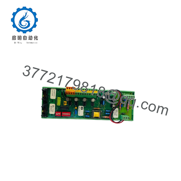
BSL-111A
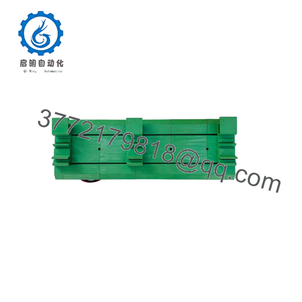
BSL-111A
Installation & Configuration Guide
1.Pre-Installation (Prep & Safety):Perform LOTO and document cabling.
- Notify central station watch officers and switch the fire alarm panel into Test/Maintenance mode.
- Isolate main 230 V AC supply and disconnect 24 V DC emergency backup batteries via Lock-Out/Tag-Out (LOTO).
- Put on a grounded wrist strap connected to the panel chassis ground terminal to prevent ESD damage.
- Photograph all wiring connections, jumper plugs, and terminal designations on the original BSL-111A card before removal.
2.Removal:Disconnect wiring and unclip module.
- Carefully unscrew or unclip terminal headers from the BSL-111A PCB assembly. Do not pull wires directly.
- Release the Phoenix Contact UMK mounting clips on the bottom rail using a small flathead screwdriver.
- Slide the board clear from adjacent card slots without applying twisting force to surrounding wiring looms.
- Seal the removed PCB in a static-shielding bag.
3.Installation (Clone & Seat):Verify jumpers and lock card into chassis.
- Unpack the New Surplus BSL-111A card on an ESD-safe workspace.
- Cross-reference configuration jumpers and revision numbers against the original module photos.
- Mount the Phoenix UMK housing onto the internal panel chassis rail until the locking clips engage securely.
- Reconnect terminal blocks according to your pre-installation wiring map.
4.Power-On & Testing:Verify DC bus rails and loop polling.
- Re-energize the main panel 24 V DC bus and reconnect battery leads.
- Check that power LEDs on the BSL-111A illuminate solid green without system ground-fault or low-voltage alarms.
- Verify that all assigned detection loops complete their initialization handshake at the central panel controller.
- Perform a functional test on at least one smoke or heat detector per loop channel to verify system trip signaling.
Firmware/Software Versions & Upgrade Notes
- System Generation: The operates as a hardware-level power distribution and interface card. It functions under native BS-100 system firmware without requiring individual board-level software downloads.
- Backward Compatibility: (P/N 7212-199.0001) serves as a direct hardware swap for older BSL-111 revisions. Always verify that pinout configurations match existing panel wiring when replacing early BSL-110 or BSL-112 interface variants.
- Electrical Safety Warning: Never attempt to adjust onboard voltage potentiometers without a calibrated digital multimeter connected. Over-volting the internal bus will damage downstream loop drivers and microcontroller cards across the backplane.
Frequently Asked Questions (FAQ)
Is this card brand new or pulled from an old vessel?
This item is a Brand New Surplus unit. It has never been installed in an active fire system, pulled from a ship breaking yard, or subject to second-hand repair. The module remains in original anti-static packaging and undergoes full quality control inspection prior to shipment.
Why should we buy New Surplus instead of used marine pulls available online?
Refurbished and used marine circuit cards frequently suffer from hidden salt-mist corrosion, dried electrolytic filter capacitors, and thermal stress on power semiconductors. While used parts appear cheaper, an unannounced power board failure on a vessel at sea can cause complete fire detection loss, leading to Class detention fines and catastrophic safety hazards.
Is the fully obsolete from the OEM?
Yes, Autronica has discontinued the BS-100 hardware platform. Sourcing New Surplus from specialized inventory allows plant operators and ship superintendents to maintain full class compliance and panel operation without spending $20,000+ on a complete panel upgrade to AutroSafe 4.
Can I swap the while the fire panel is live?
No. Never replace power supply or interface cards with panel power connected. Live insertion can cause transient voltage spikes, blowing internal line fuses or damaging sensitive microcontroller modules attached to the backplane.
Does the require software programming after installation?
No. The is a hardware power and signal conditioning interface card. Once hardware jumpers are configured to match your original board, the panel will automatically recognize the module upon power-up.



