
 WhatsApp: +86 16626708626
 Email:
  Phone: +86 16626708626
Description
Key Technical Specifications
| Parameter | Value |
|---|---|
| Manufacturer | AUTRONICA Fire and Security |
| Model | BSS-101 |
| Part Number | 7212-142.0005 |
| Product Type | Power supply module |
| Primary Function | Fire alarm system power supply |
| Application | Autronica fire detection systems |
| Installation | Autronica system/panel assembly |
| Input Voltage | Verify from module nameplate/OEM documentation |
| Output Voltage | Verify from module nameplate/OEM documentation |
| Output Current | Verify from module nameplate/OEM documentation |
| Environmental Rating | Verify from applicable system documentation |
| Replacement Status | Legacy component; verify availability and condition |
Technical accuracy note: Publicly indexed sources confirm the BSS-101 designation, function, and 7212-142.0005 part number, but I could not verify reliable OEM values for input voltage, output voltage, current capacity, dimensions, or temperature range. Those values should not be guessed for a fire-alarm power module.
Product Introduction
The AUTRONICA BSS-101 is a power supply module used in Autronica fire detection equipment. The commonly identified part number is 7212-142.0005. Its job is power conversion/distribution within the applicable Autronica system rather than detection-loop signal processing.
For replacement procurement, verify the complete part number and electrical ratings against the installed module. A BSS-101 that physically fits the panel is not automatically an electrically suitable replacement. Check the panel model, wiring, input/output requirements, and revision before energizing the system.
Installation & Configuration Guide
Stage 1: Pre-Installation Preparation — 10–15 Minutes
⚠️ Safety First: The BSS-101 is associated with fire detection equipment. Place the affected system into its approved maintenance condition and notify responsible operations/fire-safety personnel before beginning work.
Tools Required:
- ESD wrist strap
- Appropriate insulated screwdriver
- Digital multimeter
- Wire labels
- Smartphone or camera
- OEM wiring documentation
Preparation Steps:
- Record BSS-101 / 7212-142.0005 from the existing module label.
- Photograph the module from multiple angles.
- Photograph every power and signal connection before removal.
- Record the installed Autronica panel/system model.
- Record the existing power-supply configuration.
- Verify the replacement module’s identification before disconnecting the original.
- Follow the site’s lockout/tagout procedure.
Stage 2: Removing the Old Module — 5–10 Minutes
- Place the fire alarm system into its authorized maintenance state.
- Isolate the applicable power source according to the Autronica service procedure.
- Verify that hazardous voltage is absent before handling conductors.
- Label every wire before disconnection.
- Disconnect the wiring carefully; do not pull on the cable itself.
- Release the module’s mounting hardware.
- Remove the from its mounting position.
- Inspect the wiring terminals for heat discoloration, looseness, corrosion, or damaged insulation.
- Inspect the mating connectors and panel wiring.
- Keep the original module available until commissioning is complete.
Stage 3: Installing the Replacement — 5–10 Minutes
- Confirm that the replacement is , part number 7212-142.0005, or an explicitly documented approved substitute.
- Check the replacement for physical damage.
- Verify connector and terminal arrangement against the original.
- Install the module in the correct orientation.
- Secure the module mechanically.
- Reconnect each conductor according to the photographs and wiring documentation.
- Check polarity and terminal identification carefully.
- Inspect cable routing for pinching or excessive mechanical stress.
- Confirm that all terminals are properly secured.
- Perform a final visual inspection before restoring power.
Stage 4: Power-On & Testing — 10–20 Minutes
- Check the supply wiring and polarity before energizing.
- Measure the applicable supply voltage with a multimeter.
- Restore power according to the approved system procedure.
- Observe the panel and for abnormal indications.
- Check for power-supply or system fault indications.
- Verify that the fire alarm control panel starts normally.
- Check affected detection loops and system interfaces.
- Perform the required alarm and fault tests.
- Confirm that no new system fault has appeared.
- Document the replacement module’s part number and test results.
⚠️ Do not return the fire alarm system to normal operation simply because the powers up. Verify the complete system after the power supply replacement.
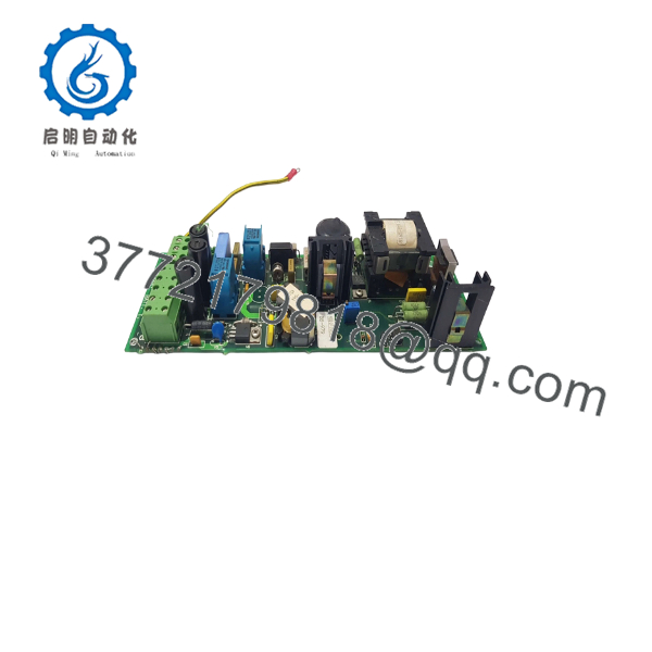
BSS-101
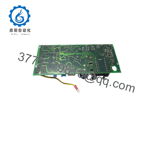
BSS-101
Frequently Asked Questions (FAQ)
What is the AUTRONICA ?
The is an Autronica power supply module used in fire detection equipment. Publicly indexed industrial-parts information identifies its part number as 7212-142.0005.
Is a detection-loop module?
No. The is identified as a power supply module, not a conventional detection-loop input/output module.
What is the part number for ?
The commonly listed part number is 7212-142.0005. Verify the number on the actual board/module before ordering because Autronica has multiple BSS-series power-supply products.
Is compatible with BSS-103 or BSS-103A?
Do not assume interchangeability. , BSS-103, and BSS-103A are separate Autronica power-supply products with different part numbers. A newer BSS-series module should only replace when the OEM documentation confirms compatibility for the specific panel.
Can I hot-swap the ?
Do not assume it is hot-swappable. For a fire detection power module, the safer procurement and maintenance approach is to isolate the applicable power source and follow the panel-specific Autronica procedure unless the OEM documentation explicitly permits live replacement.
How should I verify a replacement before buying?
Ask the supplier for photographs of the actual module, including its identification label, part number, revision, connectors, and condition. The listing should clearly state whether the unit is New Original, New Surplus, Used, or Refurbished. For a fire alarm application, also request functional-test information and warranty terms.



