
 WhatsApp: +86 16626708626
 Email:
  Phone: +86 16626708626
Description
Key Technical Specifications
| Parameter | Specification |
| Manufacturer | Autronica Fire and Security |
| Model / Part Number | CDA-20 |
| Assembly Number | 7212-020.0001 |
| System Compatibility | Autronica BS-100 / BS-60 Fire Alarm Systems |
| Primary Function | Front-panel push-button decoding, status LED driving, and local display interfacing |
| Operating Voltage | 24 V DC (Supplied via internal panel bus) |
| Interface Protocol | Autronica Parallel/Serial Display Bus |
| Mounting / Form Factor | Door-mounted sub-assembly / Internal rack interface PCB |
| Operating Temperature | −10 °C to +50 °C (+14 °F to +122 °F) |
| Storage Temperature | −40 °C to +70 °C (−40 °F to +158 °F) |
| Relative Humidity | Max. 95% non-condensing |
| Marine Classification | Certified for marine and offshore installations (DNV, Lloyd’s Register) |
Product Introduction & Supply Chain Strategy
The Autronica CDA-20 (Assembly P/N 7212-020.0001) is a specialized control and display interface board engineered for legacy Autronica BS-100 series fire alarm panels. It processes keypress inputs from the front operator fascia, controls status indicator LEDs, and maintains real-time communication between the operator interface and the central system controller.
Because Autronica officially retired the legacy BS-100 hardware series, holding this module as New Surplus is essential to maintain full site operational visibility. Purchasing factory-sealed surplus eliminates the risk of keypad unresponsiveness, dim LED indicators, or corrupted display data associated with second-hand marine pulls—ensuring your fire panel remains class-compliant without requiring a full system replacement.
Installation & Configuration Guide
1.Pre-Installation (Prep & Safety):Notify watch personnel and isolate panel power.
- Switch the fire alarm system to Maintenance/Test mode and notify duty officers or central station monitoring.
- De-energize 230 V AC main power and disconnect 24 V DC backup battery feeds via Lock-Out/Tag-Out (LOTO).
- Put on a grounded ESD wrist strap clamped to panel earth ground.
- Photograph all ribbon cables, power feeds, and DIP switches on the existing CDA-20 board before removing any connectors.
2.Removal:Disconnect display cables and unbolt module.
- Carefully unplug flat ribbon cables and terminal blocks connected to the CDA-20 header ports.
- Support the module while loosening panel door or chassis mounting standoffs.
- Remove the board smoothly to avoid snagging or flexing adjacent wiring looms.
- Place the removed unit immediately into an anti-static protective bag.
3.Installation (Clone & Seat):Match configuration jumpers and secure board.
- Unpack the New Surplus CDA-20 module inside an ESD-safe workspace.
- Verify that onboard jumpers or configuration switches match the original unit photograph taken in Stage 1.
- Align the PCB with the mounting standoffs and secure using retaining hardware.
- Reconnect all display and communication ribbon cables securely into their locking headers.
4.Power-On & Testing:Re-energize system and conduct lamp test.
- Restore 24 V DC power bus and reconnect emergency batteries.
- Verify the power LED on the CDA-20 illuminates solid green without system comms errors.
- Perform a panel “Lamp Test” function to confirm all operator fascia LEDs and display segments function properly.
- Test panel push-buttons (Silence, Reset, Test) to confirm proper input decoding by the main system CPU.
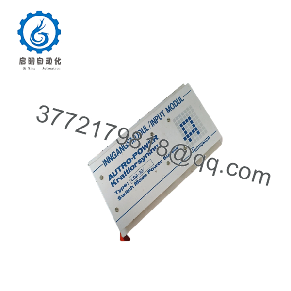
CDA-20
Firmware/Software Versions & Upgrade Notes
- System Compatibility: The operates as a hardware interface board for front-panel controls. System integration is governed by the main BS-100 central CPU firmware.
- Hardware Revisions: Ensure board revision P/N 7212-020.0001 matches your existing panel door interface layout. Connector pinouts on earlier or variant display cards may differ.
- Static Sensitivity Warning: Display drive electronics are highly sensitive to static discharge. Ungrounded handling during installation can cause latent damage to LED multiplexer ICs, leading to segment failures weeks after installation.
Frequently Asked Questions (FAQ)
Is this module genuine new surplus or a used/refurbished pull?
This item is a Brand New Surplus unit. It is not used, was never installed in a operating fire panel, and was not pulled from a decommissioned vessel. Every card undergoes non-destructive quality verification and remains in original anti-static packaging until final shipment.
Why choose New Surplus over cheaper refurbished options?
Refurbished display modules often contain aged electrolytic capacitors, worn ribbon cable connectors, and degraded LED drivers due to continuous thermal exposure inside panel enclosures. While refurbished cards cost less initially, an unexpected display failure impairs operator response during an emergency, leading to severe regulatory and safety penalties.
How do you verify the quality of obsolete parts like the ?
Each card undergoes strict inbound inspection under our SOP guidelines. We verify backplane pin conditions, inspect solder joints for micro-cracks under magnification, confirm jumper configurations, and maintain ESD-safe storage conditions at all times.
Can I replace the card while the panel is energized?
No. Replacing display interface modules with live panel power can induce static or transient voltage spikes on the internal data bus, potentially corrupting the main CPU logic or damaging adjacent display driver ICs. Always isolate power before replacement.
Does the require software reprogramming after installation?
No. The functions as a physical interface driver. Provided configuration jumpers match your original card, the main BS-100 system CPU will automatically recognize and control the display unit upon reboot.



