
 WhatsApp: +86 16626708626
 Email:
  Phone: +86 16626708626
Description
Key Technical Specifications
| Parameter | Specification |
| Manufacturer | Autronica Fire and Security |
| Model / Part Number | KDL-26B |
| Assembly Number | 7212-056.0001 |
| System Compatibility | Autronica BS-100 / BS-60 / BS-30 Fire Alarm Systems |
| Primary Function | Conventional detector loop monitoring, line fault evaluation, and alarm signal processing |
| Operating Input Voltage | 24 V DC (Supplied from internal panel backplane bus) |
| Line Supervision | End-of-line (EOL) resistor circuit monitoring for open and short circuits |
| Mounting / Form Factor | Standard Autronica rack-mount eurocard footprint |
| Operating Temperature | −10 °C to +50 °C (+14 °F to +122 °F) |
| Storage Temperature | −40 °C to +70 °C (−40 °F to +158 °F) |
| Relative Humidity | Max. 95% non-condensing |
| Marine Classification | Certified for maritime installations (DNV, Lloyd’s Register) |
Product Introduction & Supply Chain Strategy
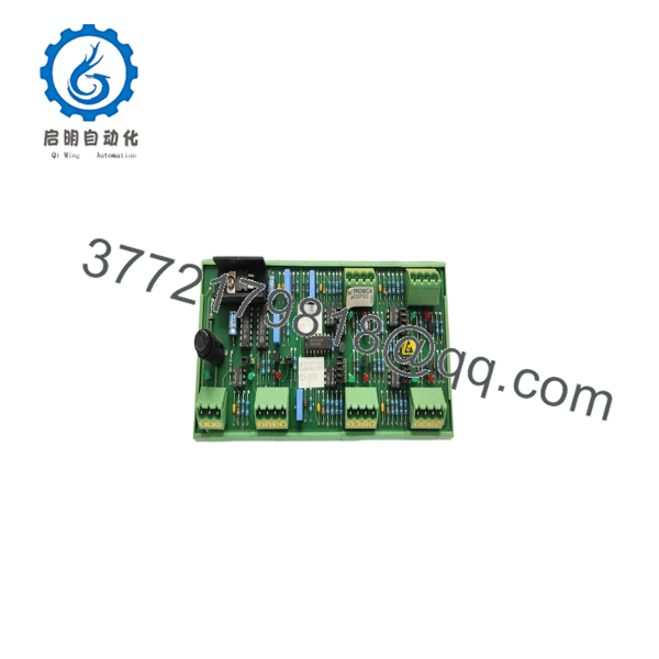
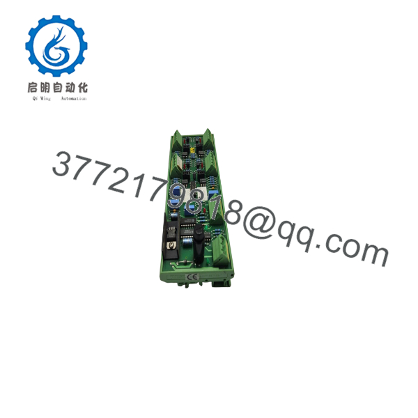
The Autronica KDL-26B (Assembly P/N 7212-056.0001) is a conventional detector loop interface board designed for legacy Autronica BS-100 series marine and industrial fire alarm systems. It monitors conventional detector zones for alarm activations, open-circuit faults, and short-circuit conditions, translating field inputs into system events for the central processing unit.
Because Autronica officially retired the legacy BS-100 architecture, keeping this module as New Surplus is essential to prevent operational downtime and vessel detention. Sourcing factory-sealed surplus eliminates the severe thermal fatigue and component drift inherent in second-hand marine pulls—guaranteeing continuous life-safety protection without forcing an unplanned, multi-thousand-dollar system overhaul.
Installation & Configuration Guide
1.Pre-Installation (Prep & Safety):Notify duty personnel and isolate panel power.
- Switch the fire alarm panel to Maintenance/Test mode and notify central watch officers.
- Execute Lock-Out/Tag-Out (LOTO) on the primary 230 V AC supply and 24 V DC backup battery feeds.
- Put on a grounded ESD wrist strap attached to the panel chassis ground.
- Photograph all detector loop wiring connections, jumper header configurations, and terminal block markings on the existing KDL-26B module before touching any wiring.
2.Removal:Disconnect terminal blocks and extract board.
- Unplug or unscrew loop wiring terminal blocks from the module faceplate without pulling directly on individual conductors.
- Loosen the upper and lower card retaining fasteners on the panel rack.
- Slide the board straight out along its guide rails to avoid bending backplane connector pins.
- Store the removed board inside an ESD-shielded protective bag.
3.Installation (Clone & Seat):Match jumpers and seat module into rack.
- Unpack the New Surplus KDL-26B board within an ESD-safe workspace.
- Check all onboard configuration jumpers and set them to match the original board configuration captured in Stage 1.
- Align the card with the designated chassis slot guide rails and push firmly until the backplane connector seats completely.
- Secure the retaining screws and reattach field wiring terminal blocks.
4.Power-On & Testing:Verify zone voltage and test detector trip.
- Restore 24 V DC system power and reconnect battery standby leads.
- Confirm power LEDs illuminate green without zone fault indicators on the main CPU panel display.
- Measure loop terminal voltages to confirm correct end-of-line (EOL) monitoring voltage.
- Test at least one conventional detector or manual call point on the connected loop to verify alarm processing and zone trip reporting.

- KDL-26B
- KDL-26B
Firmware/Software Versions & Upgrade Notes
- System Integration: The acts as a hardware line interface module within the BS-100 panel framework. It operates under main panel system firmware without requiring separate card-level software updates.
- Hardware Revisions: (P/N 7212-056.0001) serves as a direct hardware swap for earlier KDL-26 revisions. Ensure that zone end-of-line (EOL) resistor values match panel specification requirements when replacing older board variants.
- Line Termination Warning: Operating conventional loops without the proper EOL resistor values will generate continuous fault conditions or prevent genuine fire alarms from being processed by the system.
Frequently Asked Questions (FAQ)
Is this module genuine brand new surplus or a refurbished pull?
This unit is a Brand New Surplus module. It is not used, was never installed in an operational system, and was not pulled from a decommissioned vessel or plant. All cards undergo quality verification and remain in static-shielding packaging until final shipment.
Why is New Surplus superior to used or refurbished marine pulls?
Refurbished and used marine circuit cards suffer from long-term exposure to heat, vibration, and salt-laden air, which degrades input sense resistors and decoupling capacitors. While used modules appear cheaper initially, an unannounced zone failure can compromise life safety or trigger regulatory penalties that exceed initial savings.
How do you verify quality on obsolete modules like the ?
Every board undergoes non-destructive quality checks following our SOP protocol. We inspect backplane pins for straightness and insertion wear, verify PCB traces and solder joints under magnification, check jumper configurations, and enforce ESD-safe storage standards.
Can I hot-swap the card while the panel is live?
No. Hot-swapping line interface cards on legacy panels can introduce electrical transients that damage sensitive line drivers or corrupt system memory on the main CPU card. Always isolate power prior to removal or insertion.
Does the require software programming after replacement?
No. The functions as a physical detector line interface card. Once hardware configuration jumpers are set to match the original unit, the main panel controller will automatically recognize and monitor the board upon power-up.



