
 WhatsApp: +86 16626708626
 Email:
  Phone: +86 16626708626
Description
Key Technical Specifications
| Parameter | Specification |
| Operating Voltage | 24 V DC (nominal, supplied from system bus) |
| Contact Rating | 250 V AC / 30 V DC, 2 A max (resistive load) |
| Output Channels | 7 independent programmable/configurable relay contacts |
| System Compatibility | Autronica BS-100, BS-30, and customized safety control racks |
| Indication | Onboard status LEDs for power and relay activation |
| Connector Type | Edge connector / screw terminal strip |
| Operating Temp | -10°C to +55°C |
| Enclosure / Form Factor | Plug-in printed circuit board card for rack assembly |
Product Introduction & Supply Chain Strategy
The Autronica KR-30B-7 is an output relay card used within Autronica marine and industrial fire alarm detection systems. It provides reliable switching signals to initiate auxiliary safety actions—such as shutting down ventilation, closing fire dampers, and triggering external alarm bells—upon system activation.
Securing this module as New Surplus ensures immediate availability for critical vessel or facility safety systems without waiting on extended factory lead times. By selecting genuine New Surplus over high-risk refurbished cards, site engineers eliminate potential relay contact pitting and degraded solder joints, protecting safety integrity while optimizing Total Cost of Ownership (TCO).
Installation & Configuration Guide
Stage 1: Pre-Installation (Prep & Safety)
- De-energize the main fire alarm panel and isolate the 24 V DC power supply line following LOTO safety protocols.
- Strap on a grounded ESD wrist band connected to the panel enclosure chassis.
- Photograph the wiring connections and note terminal channel positions on the existing relay board.
Stage 2: Removal
- Disconnect terminal wiring blocks or ribbon cables from the card face.
- Unfasten panel retaining clips or card-edge locks holding the module in the rack frame.
- Pull the card straight outward to avoid twisting or bending backplane pins.
Stage 3: Installation (Clone & Seat)
- Verify that jumper pins or configuration links on the new KR-30B-7 match the original unit setting.
- Align the board edge into the rack guides and slide it firmly into the receiving socket.
- Secure the card locking mechanisms and re-attach all terminal connection blocks.
Stage 4: Power-On & Testing
- Restore 24 V DC system power and confirm power/status LEDs illuminate green without fault indications.
- Perform a controlled alarm loop test to verify each relay channel trips its assigned auxiliary safety equipment correctly.
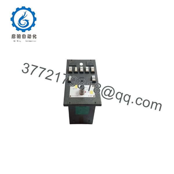
KR-30B-7
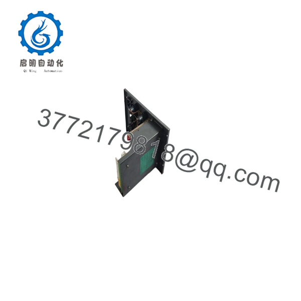
KR-30B-7
Firmware/Software Versions & Upgrade Notes
- Hardware Revisions: Ensure the sub-variant revision (suffix version -7) matches your backplane pinout and system rack layout.
- Compatibility Notice: The KR-30B series utilizes hardware logic lines from the main control panel. Confirm that the system motherboard software supports the correct relay activation table for this channel count.
- Replacement Warning: Do not modify jumper pins during hardware replacement. Incorrect jumper placement can invert relay logic (Normally Open vs. Normally Closed), causing immediate unintended equipment shutdowns upon boot.
Frequently Asked Questions (FAQ)
Q: Is this Autronica KR-30B-7 unit brand new?
A: Yes, this unit is 100% New Surplus / Original New stock. It has never been installed in an active fire system, pulled from a scrapped marine vessel, or refurbished. It remains in pristine original condition with clean connector gold pins.
Q: Why choose New Surplus over refurbished alarm boards?
A: Fire and safety systems demand zero fail rates. Refurbished relay cards often suffer from invisible coil wear, pitted relay contacts, or dry joint fatigue. New Surplus guarantees full functional lifespan and peace of mind when lives and maritime vessels depend on it.
Q: How do you verify the functionality of legacy marine electronics?
A: Each KR-30B-7 undergoes strict quality verification, including physical pin inspection, continuity checks, and live DC voltage relay actuation testing prior to anti-static seal and packaging.
Q: Can I hot-swap the KR-30B-7 module while the panel is live?
A: No. Always isolate control power prior to extracting or inserting safety system boards. Swapping cards on a powered backplane can cause transient voltage spikes, false fire alarms, or damage to main CPU bus lines.
Q: What warranty coverage applies to this board?
A: All New Surplus items come with a comprehensive 1-year functional replacement warranty. In the rare event of a component failure, we issue an immediate replacement or full credit.



