
 WhatsApp: +86 16626708626
 Email:
  Phone: +86 16626708626
Description
3. Key Technical Specifications
| Parameter | Value / Description |
|---|---|
| Manufacturer | Autronica |
| Model | NKL-5 |
| Product Type | PCB Card / Control Module |
| Typical Application | Marine automation, engine monitoring, industrial control |
| Historical Context | Related to Autronica NK-series MIP (Mean Indicated Pressure) / engine performance systems |
| Form Factor | Plug-in or chassis-mounted PCB card |
| Interface | System-specific connectors (verify on unit) |
| Power | Supplied via host system backplane or connectors |
| Environment | Marine / industrial (vibration and temperature tolerant) |
| Compatibility | Autronica NK / NKL series systems; exact match required |
| Condition Note | Configuration and revision specific – do not interchange without verification |
Exact pinout, voltage ratings, firmware/revision level, and functional mapping must be confirmed against the physical card and the original system documentation. Public datasheets for the NKL-5 are limited.
4. Product Introduction
The Autronica NKL-5 is a printed circuit board card used in Autronica marine automation and engine monitoring systems. It belongs to the broader NK / NKL family historically associated with diesel engine performance monitoring (including mean indicated pressure calculation) and related shipboard control functions.
The card is typically installed in a system chassis or rack and provides signal processing, interfacing, or control functions specific to the host Autronica installation. It is selected when a direct hardware replacement is required to restore operation of an existing system without a full redesign.
5. Installation & Configuration Guide
Stage 1: Pre-Installation Preparation (≈15 min) ⚠️ Safety First: Isolate power to the automation cabinet or engine monitoring system. Apply lock-out/tag-out. Confirm the affected system is under local supervision if it performs safety-related functions. Tools Required: ESD wrist strap and mat, appropriate screwdriver or extractor tool, multimeter, camera, anti-static packaging for the old card. Documentation: Photograph the installed card (both sides if accessible), all connector orientations, any jumpers or switch settings, and the revision markings. Note the exact location in the chassis.
Stage 2: Removing the Old Card (≈5–10 min)
- Verify zero voltage on the backplane or connectors.
- Release any retaining clips, ejectors, or screws.
- Withdraw the card straight out to avoid bending connector pins.
- Inspect the backplane connector for damage or contamination. ⚠️ Store the original card in anti-static packaging until the replacement is fully verified.
Stage 3: Installing the New Card (≈10 min)
- Confirm the incoming NKL-5 matches the removed card’s revision markings and connector layout.
- Configuration Clone (Critical): Set any jumpers, DIP switches, or address links exactly as photographed on the original card.
- Align the card with the guides and seat it firmly into the connector.
- Secure retaining hardware. Self-Checklist: [ ] Revision matches [ ] Jumpers cloned [ ] Fully seated [ ] Retaining clips locked.
Stage 4: Power-On & Testing (≈15–30 min) Pre-Power Check: Visual inspection of seating and connectors. Power-On Steps:
- Restore system power and observe card status LEDs (if present).
- Verify communication or signal presence with the host system.
- Run the system’s built-in diagnostics or perform a functional test of the monitored parameters (e.g., engine pressure signals if applicable).
- Confirm no new faults are reported by the main system.
- Document results. ⚠️ Troubleshooting Note: Incorrect jumper settings or a revision mismatch are the most common causes of “card not recognized” or abnormal readings. Always compare against the original card and system drawings.
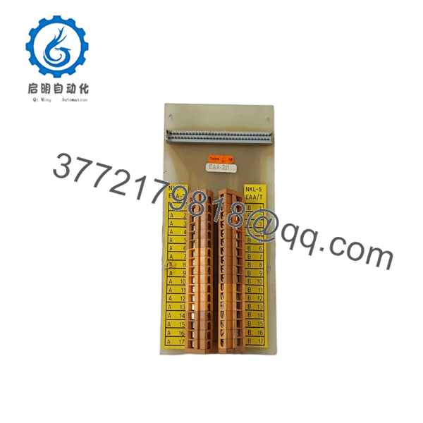
NKL-5
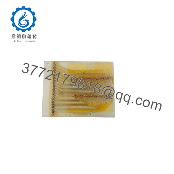
NKL-5
6. Frequently Asked Questions (FAQ)
Q: Can the NKL-5 be hot-swapped under power? No. Always isolate power before removal or insertion. Hot-swapping risks damage to the card, the backplane, and connected equipment.
Q: Is the NKL-5 still in production? This is a legacy Autronica part. Available units are typically new surplus or tested secondary-market stock. Production status should be confirmed with the supplier.
Q: Can I use any NKL-series card as a substitute? Only if the full model, revision, and connector configuration match the original. Differences in revision or option coding can prevent proper operation or produce incorrect measurements.
Q: Will system configuration or calibration be lost? Card-specific settings (jumpers, addresses) must be transferred manually. System-level calibration data normally resides elsewhere, but a full functional check is required after replacement.
Q: Why is the price lower than a modern Autronica module? These are surplus or secondary-market cards intended to keep existing systems running. Pricing reflects condition, independent testing, and residual demand rather than current OEM list pricing.
Q: What should I verify before installation? Match the exact model and revision markings, photograph and replicate all jumper/switch settings, and confirm connector orientation. Cross-check against the vessel or plant’s approved drawings whenever possible.
Q: Are test reports available? Functional test results and photographs of the nameplate/revision can be provided on request for the specific unit supplied.



