
 WhatsApp: +86 16626708626
 Email:
  Phone: +86 16626708626
Description
Key Technical Specifications
| Parameter | Value |
|---|---|
| Manufacturer | Bachmann electronic GmbH |
| Full Model | AIO288/1 |
| Product Family | AIO288/x |
| Controller Platform | Bachmann M1 automation system |
| Product Type | Analog input/output expansion module |
| Analog Inputs | 8 |
| Analog Outputs | 8 |
| Input Wiring | Single-ended or differential connection |
| Temperature Inputs | Up to 4 Pt100 or Pt1000 sensors |
| RTD Wiring Modes | 2-wire or 4-wire Pt100/Pt1000 connection |
| Potentiometer Support | Supply for up to 4 potentiometers |
| Input Fault Detection | Wire-break detection for voltage and temperature inputs |
| Output Protection | Short-circuit-proof analog outputs |
| Potentiometer Supply Protection | Overload detection |
| External Supply Monitoring | Supported |
| Typical Analog Applications | 0–10 V, 4–20 mA, RTD temperature, potentiometer position, actuator command, and process feedback |
| Module Installation | Bachmann M1 I/O station or compatible M1 system rack |
| Field Wiring Requirement | Verify exact terminal assignment, signal ranges, common references, and channel configuration in the AIO288/1 datasheet before installation |
| Lifecycle Note | Confirm the full model suffix, module revision, M1 CPU generation, terminal hardware, and installed configuration before purchase |
Bachmann specifies the AIO288/x as an analog I/O module with eight analog inputs and eight analog outputs. It supports single-ended or differential signal connections, up to four Pt100/Pt1000 sensors, 2-wire or 4-wire RTD wiring, and power for up to four potentiometers. The manufacturer also specifies wire-break detection for voltage and temperature inputs, short-circuit protection for outputs, potentiometer-supply overload detection, and external-supply monitoring.
Product Introduction
The Bachmann AIO288/1 is an analog input/output module for the Bachmann M1 automation platform. It combines eight configurable analog inputs with eight analog outputs in one module for industrial machines, power-generation systems, process skids, test stands, and distributed-control panels. The module supports process measurement, temperature acquisition, position feedback, analog command signals, and actuator control.
The AIO288/1 is especially useful where one I/O card must handle mixed analog duties: voltage or current transmitters, Pt100/Pt1000 RTDs, potentiometers, and analog output commands. Confirm the existing channel configuration before replacement. A module that physically fits the M1 station can still create bad measurements or output commands if the site expects a different signal range, wiring mode, sensor type, or field common arrangement.
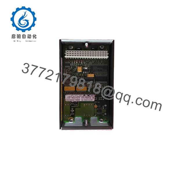
AIO288/1
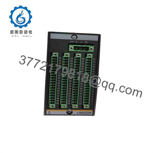
AIO288/1
Troubleshooting Quick Reference
| Symptom | Possible Cause | Relevance to this Part | Quick Check Method | Recommendation |
|---|---|---|---|---|
| All analog inputs read zero or invalid | Missing module power, M1 rack communication issue, module not seated, wrong hardware configuration | ⚠️ Medium | Check M1 CPU diagnostics, rack supply voltage, module seating, and configured I/O station address | Confirm system power and configuration before replacing the /1 |
| One 4–20 mA channel reads 0 mA | Open loop, failed transmitter, missing loop supply, blown fuse, broken field cable | ❌ Low | Measure loop current in series with a calibrated meter; verify transmitter power and field terminal continuity | Repair the loop before replacing the input module |
| One analog input reads a fixed high value | Shorted signal wiring, transmitter saturated, wrong configured input range, failed channel | ⚠️ Medium | Measure the actual field signal at the module terminal and compare it to the raw value in the M1 application | Correct transmitter range or configuration first. Replace the module only if a verified signal is misread |
| RTD temperature reads open circuit or extreme low temperature | Broken RTD lead, incorrect 2-wire/4-wire configuration, wrong Pt100/Pt1000 selection, loose terminal | ⚠️ Medium | Measure RTD resistance at the terminal; verify sensor type and wiring method in the application | The module supports wire-break detection for temperature inputs. Confirm wiring and sensor type before replacing the module |
| RTD reading is consistently offset | Incorrect RTD type, lead resistance in 2-wire circuit, wrong scaling, poor terminal contact | ❌ Low | Compare with a calibrated resistance decade box or temperature calibrator; check sensor type and lead resistance | Use 4-wire wiring where high accuracy matters. Correct configuration before replacing hardware |
| Input value jumps when motors or VFDs start | Ground loop, shield problem, analog common error, noise coupling, unstable sensor supply | ⚠️ Medium | Trend the signal during motor starts; inspect shielding, analog common, cable routing, and supply voltage | Separate analog cables from power conductors and correct grounding before replacing the card |
| Potentiometer feedback stays at zero or maximum | Missing potentiometer excitation, incorrect wiper wiring, pot failure, overload trip | ⚠️ Medium | Measure the potentiometer supply and wiper voltage; inspect pot resistance while moving the mechanism | Verify field wiring and mechanical linkage. The module monitors potentiometer-supply overload conditions |
| Potentiometer supply reports overload | Shorted excitation wiring, failed potentiometer, wiring to wrong terminal, cable damage | ⚠️ Medium | Disconnect the pot wiring, reset the condition, and measure resistance from excitation terminals to common | Repair the field circuit before reconnecting. Do not repeatedly reset a shorted potentiometer supply |
| Analog output command changes in software but actuator does not move | Open output loop, missing actuator power, wrong output range, failed actuator input, incorrect common | ⚠️ Medium | Measure the output signal directly at the module terminal and then at the actuator input while commanding a known value | If the module output is correct, troubleshoot actuator wiring and the final element—not the /1 |
| Analog output trips or clamps | Output short circuit, overloaded output, wiring fault, failed external interface | ✅ High | Disconnect the field load under approved conditions; test output with a suitable high-impedance meter or approved load | The outputs are short-circuit proof. Remove the field short before declaring the output channel faulty |
| Output value is offset or inverted | Wrong output scaling, incorrect 0–10 V versus 4–20 mA configuration, reversed signal wiring, application logic issue | ❌ Low | Command known values such as 0%, 50%, and 100%; compare terminal measurement against configuration | Correct output range and scaling. Do not replace the module because a software range is wrong |
| Replacement module works but channels map to wrong field points | Module inserted in wrong slot, application configuration mismatch, terminals cross-wired, incorrect project download | ✅ High | Compare the old slot, terminal labels, I/O configuration, and test each channel with isolated loads | Validate every input and output one channel at a time before returning the machine to automatic operation |
| Several analog channels fail after a cabinet event | Common supply loss, shared ground disconnected, external supply failure, surge damage | ⚠️ Medium | Measure external supply at the module, inspect common terminals, and review cabinet-event history | Check shared field power and grounding first. Multiple failed channels rarely indicate separate internal faults |
| Module is not recognized after replacement | Incompatible M1 CPU/firmware, incorrect module revision, backplane contact issue, stale hardware configuration | ⚠️ Medium | Verify M1 controller model and firmware, reseat the module, inspect connectors, and update the approved hardware configuration | Confirm compatibility and project configuration before returning the system to service |
❗ Signal-range warning: Do not assume every channel is configured alike. A 4–20 mA input, a 0–10 V input, a Pt100 RTD, and a potentiometer feedback channel require different wiring and application settings. Photograph the existing terminal wiring and export the M1 project before removal.
❗ RTD warning: A Pt100 and Pt1000 are not interchangeable. Selecting the wrong sensor type can make a normal process temperature appear wildly incorrect. Verify the sensor marking, wiring method, and configured input type before replacing the module.
❗ Analog-common warning: Do not use an analog input common as a convenient power return for unrelated field devices. Shared noise or current can create unstable readings across multiple channels.
❗ Output warning: The analog outputs are short-circuit proof, but that does not make them suitable for driving solenoids, relays, or motor loads directly. Use analog outputs only with properly rated analog-input devices, isolators, positioners, drives, or signal conditioners.
If troubleshooting remains unresolved, provide technical support with photos of the /1 label, M1 rack location, terminal wiring, power supply, controller diagnostics, configuration screenshots, field device model, and measured signal values at the module terminals.
Frequently Asked Questions
What does the Bachmann /1 do?
The /1 adds eight analog inputs and eight analog outputs to a Bachmann M1 control system. It can be used for analog process signals, temperature inputs, potentiometer feedback, and analog actuator-command outputs.
Can the /1 read Pt100 and Pt1000 temperature sensors?
Yes. Bachmann specifies support for up to four Pt100 or Pt1000 sensors, using either 2-wire or 4-wire wiring. Four-wire RTD wiring gives better measurement accuracy because it compensates for lead resistance.
Can I connect voltage and current signals to the same /1?
The /x family is designed for mixed analog applications, but the allowed channel combinations and configuration method must be verified in the /1 datasheet and installed M1 project. Confirm the exact channel mode, wiring, field common, and signal range before connecting voltage or current devices.
Does this module detect broken sensor wiring?
Yes. Bachmann specifies wire-break detection for voltage and temperature inputs. This helps identify open field wires or failed RTD leads, but you should still verify the actual signal at the terminal with a meter before replacing the module.
Are the analog outputs protected against short circuits?
Yes. The manufacturer specifies short-circuit-proof outputs. If an output is in protection state, disconnect the external load and inspect the wiring before replacing the module. The common cause is a damaged actuator cable, shorted input circuit, or incorrect field connection.
Can I hot-swap the /1?
Do not assume hot-swap capability unless the installed Bachmann M1 system and your approved maintenance procedure specifically allow it. Before removing the module, identify which outputs control active equipment, place the machine or process in a safe state, record output values, isolate field circuits as required, and use ESD protection.
Why does my 4–20 mA input show the wrong value?
First measure the actual loop current. If the transmitter produces the expected current but the application value is wrong, inspect the input range, engineering scaling, analog common, channel configuration, and terminal connection. If the measured current itself is wrong, troubleshoot the transmitter, loop supply, wiring, barrier, or isolator before blaming the /1.
Why does the analog output change in the PLC but not at the actuator?
Measure the output at the /1 terminal first. If the expected voltage or current is present there, the module is working and the fault is downstream: cable, isolator, valve positioner, VFD analog input, or actuator power. If the terminal signal is wrong with confirmed configuration and no shorted load, investigate the module output channel.
Is /1 obsolete?
The /1 belongs to an established Bachmann M1 I/O family, but lifecycle status depends on the exact hardware revision and local distribution channel. For critical installations, maintain tested spares and preserve the M1 project, firmware information, terminal drawings, and channel configuration. Verify current factory availability separately from used or surplus inventory.
What condition should I request for a production-critical spare?
Request New Original / New Surplus with full label, packaging, module-revision, and connector photos. For Refurbished (tested) stock, request documented tests for all eight analog inputs, all eight analog outputs, RTD simulation, potentiometer supply, wire-break detection, output short-circuit protection, external-supply monitoring, rack recognition, and sustained runtime. Ask for test photos or video, confirmed stock, warranty, and return terms before purchase.



