
 WhatsApp: +86 16626708626
 Email:
  Phone: +86 16626708626
Description
Specifications
| Parameter | Specification |
|---|---|
| Model | BES212N |
| Common Part Designation | BES212/N |
| Manufacturer | Bachmann electronic |
| Product Family | M1 |
| Product Type | Bus Expansion Slave Module |
| Primary Function | M1 system-bus expansion |
| Supply Voltage | 18–34 VDC |
| Nominal Supply | 24 VDC |
| Maximum Current | 1.2 A at 24 VDC |
| Auxiliary Outputs | +5 V / 2 A; +15 V / 250 mA; −15 V / 200 mA |
| Communication Ports | 2 × RJ45 |
| Cable | Dedicated CAT7 bus cable |
| Topology | Daisy-chain |
| Maximum Substations | 6 |
| Modules per Substation | Up to 15 M200 standard modules |
| Maximum Station-to-Station Distance | 3 m |
| Access Latency | <1.5 µs |
| Operating Temperature | −30 to +60 °C |
| Storage Temperature | −40 to +85 °C |
| Protection Class | IP20 |
| Weight | Approximately 0.5 kg |
The BES212/N is identified as a Bachmann M1 Bus Expansion Slave Module. Current industrial listings associate BES212N and BES212/N with the same M1 bus-expansion hardware, while available technical descriptions specify two RJ45 interfaces, 18–34 VDC supply, daisy-chain expansion, up to six substations, and up to 15 M200 modules per substation.
The supplied designation BES212N is commonly written BES212/N in product listings. Confirm the nameplate before procurement, particularly where the replacement must match a specific Bachmann hardware revision.
Product Introduction
The Bachmann BES212N is an M1 system-bus expansion module used to extend distributed I/O and automation hardware beyond the primary M1 station. It provides a high-speed link between the main control system and additional M200 modules installed in remote substations.
The module uses two RJ45 interfaces for the dedicated expansion connection and supports a daisy-chain architecture. The published specifications indicate up to six substations, with each substation supporting up to 15 M200 standard modules and a maximum 3 m distance between adjacent stations.
Installation Guide
Stage 1 — Pre-Installation
- Apply the plant’s approved lockout/tagout procedure.
- Isolate the 24 VDC control supply before removing the module.
- Back up the existing M1 configuration and document the current station arrangement.
- Photograph both RJ45 connections and the module’s power wiring.
- Record the position of the BES212N within the M1 expansion chain.
- Verify the replacement designation as BES212N / BES212/N.
- Confirm that the available replacement uses the same Bachmann M1 bus architecture and hardware revision.
Stage 2 — Remove the Existing Module
- Verify that the module is fully de-energized.
- Label both communication cables before disconnecting them.
- Disconnect the 24 VDC supply and auxiliary wiring.
- Disconnect the RJ45 expansion cables without damaging the connectors.
- Release the module from its mounting arrangement.
- Inspect the connectors and surrounding modules for contamination or mechanical damage.
- Check the dedicated expansion cables for cuts, crushed sections, or incorrect routing.
Stage 3 — Install the
- Install the replacement module in the same M1 station position.
- Confirm the supply voltage is within the specified 18–34 VDC range.
- Reconnect the two expansion cables according to the original topology.
- Use the specified dedicated cable arrangement; the available technical description identifies CAT7 cabling for the expansion connection.
- Verify that the station-to-station distance remains within the documented 3 m maximum.
- Restore auxiliary power connections where required.
- Check that the total number of connected substations and M200 modules remains within the documented architecture limits.
Stage 4 — Power-Up and Functional Test
- Inspect all power and communication connections before energizing.
- Apply the 24 VDC supply and check the module status indication.
- Verify communication between the primary M1 station and the expanded station.
- Confirm that downstream M200 modules are recognized correctly.
- Check I/O data exchange from representative modules.
- Verify the complete daisy-chain for communication interruptions.
- Monitor the system for bus faults or station dropouts.
- Confirm normal operation before returning the equipment to production.
Technical pitfall: The is not simply an Ethernet switch. Its RJ45 connectors form part of the Bachmann M1 bus-expansion architecture. Substituting a standard Ethernet cable or network switch without confirming the system’s cabling requirements can create a communication failure even when the connectors physically fit. The available technical listing specifically describes the ports as part of the dedicated high-speed bus-expansion connection.
For surplus or refurbished stock, supplier QC should include visual inspection, 24 VDC power-up testing, both port checks, M1 bus communication testing, downstream module recognition, auxiliary-output verification where applicable, and final part-number/revision inspection. These tests should only be described as completed when supported by an actual test record.
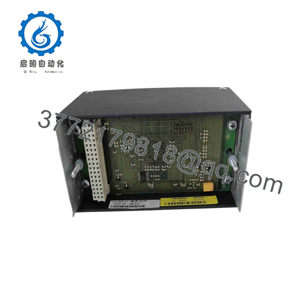
BES212/N
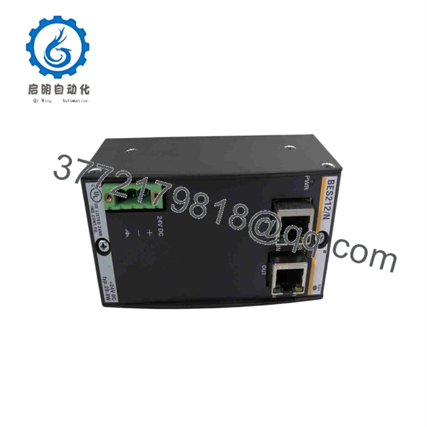
BES212/N
FAQ
1. What is the Bachmann ?
The , commonly designated BES212/N, is a Bachmann M1 Bus Expansion Slave Module used to extend the M1 system bus to distributed stations.
2. What voltage does the require?
The available technical specification lists an 18–34 VDC supply range, with 24 VDC as the nominal operating supply.
3. How many remote substations can one support?
The published specification indicates up to six substations in the daisy-chain architecture.
4. How many modules can be installed at each substation?
The available specification lists up to 15 standard modules per substation.
5. What is the maximum distance between expansion stations?
The published specification gives a maximum distance of 3 meters between adjacent stations.
6. Is the same as /N?
Industrial listings use both and for this Bachmann module. For an exact replacement, match the complete nameplate designation and hardware revision rather than relying only on punctuation in the catalog number.
7. What should I verify before purchasing a used or surplus ?
Verify the complete model designation, hardware revision, 24 VDC operation, connector condition, M1 bus communication, auxiliary outputs, and actual functional-test results. Also confirm the existing system’s expansion topology and cable arrangement before installation.



