
 WhatsApp: +86 16626708626
 Email:
  Phone: +86 16626708626
Description
Key Technical Specifications
| Parameter | Value |
|---|---|
| Manufacturer | BACHMANN electronic GmbH |
| Model | DIO280 |
| Standard Part Number | 00019114-00 |
| Cold-Climate Variant | DIO280 CC, 00019119-00 |
| Product Type | Isolated digital input/output module |
| Automation Platform | BACHMANN M1 controller system |
| Total Channel Capacity | 80 channels |
| Dedicated Digital Inputs | 32 channels |
| Dedicated Digital Outputs | 32 channels |
| Configurable DIO Channels | 16 channels configurable as input or output |
| Digital Input Voltage, ON | 15–34 V DC |
| Digital Input Voltage, OFF | 0–5 V DC |
| Output Voltage Range | 18–34 V DC |
| Nominal Field Supply | 24 V DC |
| Maximum Output Current per Channel | 0.5 A |
| Maximum Total Output Current | 24 A |
| Output Groups | 6 groups |
| Input Filter | Configurable, 10 µs to 270 ms |
| Interrupt Inputs | 8 configurable channels |
| Counter Functions | Up to 4 configurable 32-bit counters |
| Counter Modes | Event counting, incremental encoder, gate-time, period-duration, and frequency measurement |
| Maximum Counter Frequency | 50 kHz single-channel; 20 kHz dual-channel |
| PWM Function | Supported for outputs, including valve economy control |
| PWM Hold Time | Configurable from 0 to 2 s |
| Maximum Switching Frequency | 1 kHz with resistive load |
| Inductive Breaking Capacity | 1.15 H |
| Channel Status Indication | Green LED per channel |
| External Supply Range | 18–34 V DC |
| Reverse-Polarity Protection | Yes |
| Internal 5 V Current Consumption | 180 mA |
| Isolation | Isolated module design |
| Terminal Set | KZ-DIO280 B+C, Part Number 00011978-50, available separately depending on supply scope |
BACHMANN specifies the DIO280 as a high-density module with 32 dedicated inputs, 32 dedicated outputs, and 16 channels configurable as either inputs or outputs. The same official documentation specifies 24 V DC operation, 0.5 A maximum per output channel, six output groups, configurable filtering, PWM, interrupt handling, and counter functions.
Product Introduction
The BACHMANN DIO280, Part Number 00019114-00, is an M1-series 24 V DC digital input/output module with 80 total channels: 32 dedicated digital inputs, 32 dedicated digital outputs, and 16 configurable DIO channels. It is used in industrial machinery, process equipment, power-generation controls, and wind-turbine automation where a controller must read field devices and operate discrete loads from one M1 rack module.
The DIO280 combines standard I/O with functions normally requiring separate specialty cards: input filtering, eight interrupt inputs, four 32-bit counters, encoder processing, frequency measurement, and PWM output control. It is a practical choice when cabinet space and M1 rack slots matter, but output-group loading and field-supply sizing must be calculated before installation.
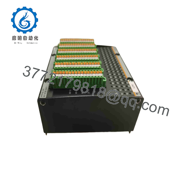
DIO280
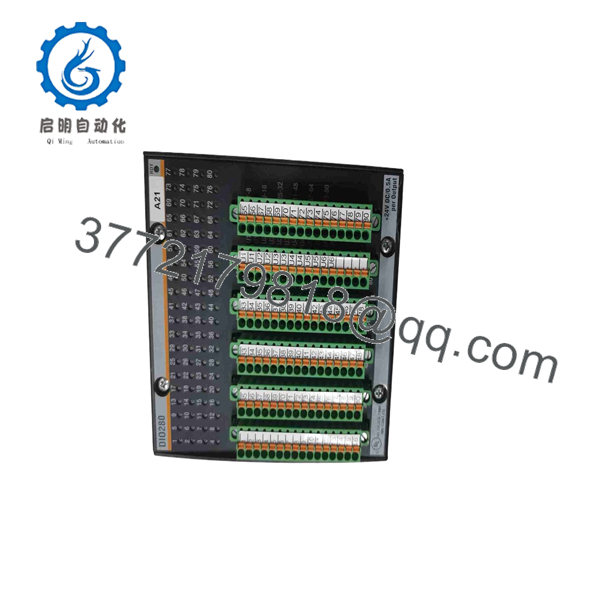
DIO280
Troubleshooting Quick Reference
| Symptom | Possible Cause | Relevance to This Part | Quick Check Method | Recommendation |
|---|---|---|---|---|
| No channel LEDs illuminate after power-up | Missing 24 V DC field supply, missing M1 rack logic power, reversed external supply, loose module seating | ⚠️ Medium | Measure the external supply at the power terminals. Confirm 18–34 V DC and correct polarity. Verify M1 rack power supply status and inspect module seating. | Restore power and reseat the module before replacing it. The has reverse-polarity protection, but do not rely on that as a wiring test method. |
| All outputs in one section fail together | Shared output-group supply loss, blown fuse, open common, overloaded group, field wiring fault | ❌ Usually low | Identify whether failed outputs share a common output group. Measure the group supply at the module terminals and compare with a working group. | Check group fuses, common wiring, and load current before condemning the . |
| One output LED changes but the load stays off | Open load circuit, failed relay coil or solenoid, incorrect field common, damaged conductor, output channel fault | ✅ Medium | Command the output on. Measure voltage at the output terminal and then directly across the load. Check continuity with power isolated. | If output voltage is present at the module but missing at the load, repair field wiring or the device. If no output voltage is present with a valid command, investigate that channel. |
| Output turns on briefly, then drops out | Overcurrent, inductive-load kickback, group current limit, wrong PWM setting, logic interlock | ⚠️ Medium | Check controller diagnostics and output LED behavior. Measure coil current with a clamp meter. Compare the result with the 0.5 A maximum per channel and 24 A total module limit. | Add properly rated suppression at inductive loads and correct the load design. Do not use the card as a substitute for a fused output distribution system. |
| Digital input never turns on | Sensor supply missing, sensor output type mismatch, broken wire, incorrect input common, failed input channel | ✅ Medium | Energize the field device and measure voltage at the exact input terminal. A valid ON level is 15–34 V DC. Compare with a known-good input. | If proper voltage reaches the terminal but the input LED and controller status remain off, the channel may be defective. |
| Digital input remains on with field device off | Cable short, leakage current, wiring cross-connection, incorrect sensor wiring, failed input circuit | ⚠️ Medium | Disconnect the field wire under approved lockout conditions. If the LED remains on, inspect the input circuit and module. If it turns off, trace the external cable or sensor. | Correct field wiring before replacing the module. |
| Fast encoder or counter misses pulses | Incorrect counter mode, wrong channel pairing, input filter too long, signal frequency exceeds limit, poor shielding | ⚠️ Medium | Review M1 configuration for counter mode and input filter. Scope the signal at the input terminal. Compare frequency with the 50 kHz single-channel or 20 kHz dual-channel limit. | Use the correct counter mode and reduce input filtering only after confirming signal quality. Check shield termination per the installation standard. |
| PWM valve does not hold correctly | Incorrect PWM frequency, hold time disabled, load current too high, valve coil incompatible, missing flyback suppression | ✅ Medium | Verify PWM and hold-time settings in the M1 application. Measure coil current and inspect output waveform with an approved meter or oscilloscope. | Confirm the valve data sheet and configure PWM to match the coil. The supports configurable hold time from 0 to 2 s for valve economy operation. |
| Module reports errors after replacement | Wrong hardware variant, terminal set mismatch, module not seated, incorrect I/O configuration, field wiring moved incorrectly | ✅ High | Compare labels, part number, terminal-block type, rack location, and M1 project hardware configuration with the removed unit. | Match 00019114-00 exactly unless engineering has approved CC or another replacement. Back up the M1 project before any hardware change. |
| Module becomes warm or output group trips under load | Excessive channel current, excessive combined module current, shorted solenoid, poor cabinet ventilation | ✅ High | Use a clamp meter to check each active load. Sum output current across channels and compare with the 24 A maximum total output rating. | Reduce loading, use interposing relays where appropriate, and keep at least a 20% power margin in the field-supply design. |
❗ Critical warning: Do not wire outputs from memory. The has 80 channels and six output groups. A misplaced common or field supply can energize the wrong actuator, damage an output channel, or create a process hazard. Photograph the original terminal blocks and wire markers before removal.
❗ ESD warning: I have watched technicians handle high-density I/O cards in dry winter air without a grounding strap, then discover an intermittent channel fault after startup. Use a grounded ESD wrist strap, place the module on an ESD-safe surface, and do not touch connector contacts.
If the module fault remains unclear, provide technical support with M1 diagnostics, label and revision photos, rack slot information, terminal photos, controller project hardware configuration, and voltage/current readings from the affected channels.
Frequently Asked Questions
What does the BACHMANN do?
The BACHMANN is a high-density M1 digital I/O module. It reads 24 V DC field signals from sensors, switches, and contact outputs, while switching 24 V DC loads such as contactors, interposing relays, pneumatic valves, hydraulic valves, lamps, and solenoids. BACHMANN specifies 32 digital inputs, 32 digital outputs, and 16 channels configurable as either inputs or outputs.
How many I/O points does have?
The provides 80 total channels: 32 dedicated digital inputs, 32 dedicated digital outputs, and 16 configurable digital I/O channels. The configurable channels can be set as inputs or outputs, so the final input/output ratio depends on the M1 project configuration.
What voltage does the use?
The module uses a nominal 24 V DC external supply and accepts an external supply range of 18–34 V DC. BACHMANN lists the digital-input ON range as 15–34 V DC and the OFF range as 0–5 V DC. Its output operating range is 18–34 V DC.
How much current can each output supply?
Each output channel is rated for a maximum of 0.5 A. The module’s maximum combined output current is 24 A. The real-world limit is often lower because you must also account for field-supply capacity, output-group fusing, ambient temperature, cable voltage drop, inrush current, and inductive-load behavior.
Can I drive solenoids directly from outputs?
Often yes, provided each solenoid stays within the 0.5 A per-channel limit and the module’s total output current remains below 24 A. But check coil inrush, DC resistance, duty cycle, and inductive suppression. For large solenoids, contactors, heaters, or uncertain loads, use an interposing relay or properly rated external driver. The supports PWM, including a configurable 0–2 s hold time for valve economy control.
Can I use for encoder pulses or frequency measurement?
Yes. The module provides up to four configurable 32-bit counters and supports event counting, incremental encoder operation, gate-time measurement, period-duration measurement, and frequency measurement. BACHMANN specifies maximum counter frequencies of 50 kHz in one-channel mode and 20 kHz in dual-channel mode.
Is the same as CC?
No. CC is a cold-climate variant identified by BACHMANN as Part Number 00019119-00, while the standard is Part Number 00019114-00. Do not assume they are interchangeable without confirming the environmental rating, installed hardware configuration, approved project documentation, and site engineering requirements.
Can I hot-swap the ?
Do not assume hot swapping is permitted. Isolate rack and field power unless the official M1 documentation and your site maintenance procedure explicitly authorize a controlled replacement. The output side can drive real machinery. Removing the card live can cause false inputs, actuator movement, output faults, or backplane damage.
Will I lose my M1 controller program if I replace ?
Normally, no. The M1 application resides in the controller rather than the I/O module. However, replacing the module can still create startup faults if the hardware configuration does not match the installed part number, configurable channels are set differently, the wrong terminal set is used, or field wiring is restored to the wrong terminals.
What should I request when buying New Surplus or refurbished stock?
Request photos of the exact label, Part Number 00019114-00, hardware revision, connector faces, terminal blocks, packaging, and any included accessories. For a refurbished module, request a functional test report covering power-up, M1 rack recognition, digital input simulation, output switching under load, LED operation, counter-function checks where required, and a written warranty. Official BACHMANN documentation lists the corresponding terminal set as KZ- B+C, Part Number 00011978-50; verify whether it is included or needs to be ordered separately.



