WhatsApp: +86 16626708626
 Email:
 Phone: +86 16626708626
Description
Core Product Summary (Brand / Model / Key Attributes)
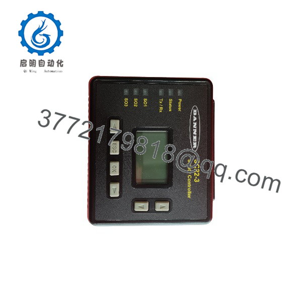
The Banner SC22-3-C (Part Number 77913) is a fully configurable, base-unit safety controller belonging to the Banner SC22 series. Designed to replace multiple dedicated safety modules in complex industrial machinery, this compact safety logic device monitors up to 22 input channels to manage emergency stops, safety light curtains, interlocking switches, protective gates, two-hand controls, and safety mats within a unified safety architecture.
Operating on a 24 V DC supply, the SC22-3-C features 22 configurable inputs, 3 independently controlled dual-channel solid-state PNP safety outputs (OSSD pairs rated at 0.75 A each), and 10 non-safety PNP auxiliary status outputs (1.0 A total load) for system diagnostic signaling. The unit incorporates removable cage-clamp terminal blocks, a backlit LCD front-panel interface, a USB programming port, and a removable external memory card slot for seamless configuration storage and transfer. It is engineered for high-integrity safety applications demanding SIL 3 (IEC 61508 / IEC 62061), Category 4, and Performance Level e (EN ISO 13849-1) compliance.
Key Technical Specifications
| Parameter | Specification |
| Brand & Model | Banner Engineering SC22-3-C (Part No. 77913) |
| Device Type | Configurable Base Safety Controller |
| Supply Voltage | 24 V DC |
| Power Consumption | 0.4 A (controller base without load); 5.9 A (maximum total system load) |
| Total Inputs | 22 configurable inputs (supports solid-state PNP and dry-contact inputs) |
| Safety Inputs (Dry Contact) | Dual-channel: 8 to 50 mA @ 24 V DC |
| Safety Inputs (Solid-State) | Dual-channel: 50 mA @ 15 to 30 V DC |
| Safety Outputs | 3 dual-channel PNP OSSD pairs (independently controlled) |
| Safety Output Rating | 0.75 A max. per OSSD pair @ 24 V DC |
| Non-Safety Status Outputs | 10 single-channel PNP outputs |
| Status Output Rating | 0.5 A max. per output; 1.0 A max. cumulative total @ 24 V DC |
| User Interface | Backlit LCD screen with diagnostic LEDs and keypad (Onboard Interface) |
| Programming Options | PC Interface (PCI) software via USB, or Onboard Interface (OBI) |
| Removable Storage | External Memory Card included |
| Terminal Block Type | Removable cage-clamp wiring connectors |
| Mounting Standard | 35 mm DIN rail mount |
| Enclosure Rating | IP20 |
| Dimensions (H × W × D) | 112 mm × 131 mm × 64 mm |
| Operating Temperature | 0°C to +55°C |
| Safety Ratings | SIL 3 (IEC 61508 / IEC 62061), Category 4 / PL e (EN ISO 13849-1) |
Detailed Product Overview
The Banner SC22-3-C provides flexible, software- and panel-configurable safety control designed to consolidate complex hardwired safety circuits into a single DIN-rail mounted module. By offering 22 fully configurable input terminals, the controller accommodates diverse protective hardware configurations without requiring multiple single-function safety relays.
The device integrates two primary methods of logic configuration: a free PC Interface (PCI) software tool connected via USB, and an Onboard Interface (OBI) utilizing the built-in monochrome backlit LCD display and pushbuttons. Logical functional blocks—such as ON-Delay, OFF-Delay, cancel OFF-Delay, external device monitoring (EDM), reset options, and bypass or muting functions—can be assigned directly to input devices and mapped to output pairs.
Output capability is separated into two functionally isolated tiers:
- Safety Outputs: Three independent, dual-channel PNP OSSD pairs designed to switch up to 0.75 A per pair. These outputs drive safety contactors, control power disconnects, or enable drives directly with integrated short-circuit and cross-fault monitoring.
- Auxiliary Status Outputs: Ten discrete PNP status outputs designed to communicate current input status, fault modes, output readiness, or reset states to supervisory control systems such as standard PLCs or HMIs.
To ensure field reliability and rapid servicing, configuration files stored in internal flash memory can be backed up directly to the included removable memory card. This hardware-based backup allows rapid module replacement without requiring a PC on the plant floor. Wiring is completed via pluggable cage-clamp terminal blocks, enabling quick module replacement during field service.
SC22-3-C
SC22-3-C
System Compatibility & Integration Requirements
| Item / Dependency | Verified Compatibility or Requirement | Practical Note |
| Primary Power Supply | 24 V DC (±15% smoothed) | Requires standard industrial 24V DC class 2 power source capable of delivering up to 5.9 A under full output loading. |
| Input Devices | E-stops, Interlocks, Light Curtains, Two-Hand Control, Rope Pulls, Safety Mats | Supports both PNP solid-state OSSD sources and mechanical dry-contact safety devices. |
| Output Interfacing | Safety Contactors, Forced-Guided Relays, Variable Frequency Drive Safety Inputs | OSSD outputs provide pulse testing; load impedance must accommodate short test pulses without dropping out. |
| Programming Tool | Banner Safety Controller PC Interface (PCI) v2.0 or higher | Programming interface connects via direct USB connection. |
| Wiring Connection | Spring-loaded Cage-Clamp Pluggable Terminal Blocks | Included with SC22-3-C kit. Accommodates standard industrial control panel wire gauges. |
| Backup Storage | Proprietary Banner Removable Memory Card | Included in kit; retains verified system configuration for off-line storage or unit duplication. |
Engineering Selection Highlights
- Input Flexibility: Accepts dry-contact switches, solid-state PNP outputs, optical light curtains, and safety mats across 22 configurable channels.
- Multi-Zone Safety Architecture: 3 independently programmable OSSD pairs allow distinct safety zones or staged shutdown sequences on a single machine.
- No-PC Maintenance Swaps: System configuration is backed up to a physical removable card, enabling maintenance personnel to clone settings directly to a replacement unit.
- Separation of Safety and Auxiliary Data: 10 non-safety status outputs handle standard PLC feedback without consuming high-integrity safety outputs.
- Removable Cage-Clamp Wiring: Simplifies installation and reduces downtime during module replacement by eliminating individual lead re-wiring.
- High Safety Standard Compliance: Certified for SIL 3, Category 4, and PL e applications.
Dimensions, Mounting & Connection Notes
- Dimensions: 112 mm Height × 131 mm Width × 64 mm Depth.
- Mounting Standard: Standard 35 mm DIN rail mounting.
- Protection Class: IP20 rated; must be installed inside an NEMA 12 / IP54 or better enclosure to protect against dust and conductive contamination.
- Connection Type: Removable cage-clamp terminal headers provided with the controller kit.
- Thermal & Environmental Limits: Designed for operating ambient temperatures between 0°C and +55°C at a relative humidity up to 90% at 50°C (non-condensing).
FAQ
What is the Banner SC22-3-C?
The Banner SC22-3-C is a 24V DC fully configurable safety controller engineered to manage multiple machine safety input devices and output circuits through a single logic base module.
What does the “-C” suffix denote in the model number?
The “-C” suffix indicates that the controller kit includes removable cage-clamp terminal blocks alongside the standard removable memory card.
How many safety devices can the SC22-3-C monitor?
The controller features 22 configurable input channels that can be mapped to dry-contact or PNP solid-state safety devices, including light curtains, emergency stops, gate switches, and safety mats.
What are the output capacity specs for the safety outputs?
It features 3 independently controlled dual-channel solid-state PNP safety output pairs (OSSDs), with each pair rated for up to 0.75 A at 24 V DC.
Can the SC22-3-C be programmed without a computer?
Yes. Basic programming, settings adjustments, and configuration checks can be executed directly on the module using the built-in backlit LCD and control pushbuttons via the Onboard Interface (OBI).
How are configurations backed up or replaced?
The unit features a slot for a removable external memory card, allowing the complete configuration file to be saved and transferred directly to another module without requiring a computer.
Verification & Troubleshooting Notes
- Power & Status LEDs: A green LED indicates active primary 24V DC power supply; a red LED indicates a system fault or that safety outputs are in the OFF state.
- LCD Error Display: The backlit Onboard Interface displays specific system faults, configuration mismatch codes, or lockout states directly on screen for rapid field diagnostics.
- Lockout Recovery: System lockouts generally stem from external wiring cross-faults, supply voltage fluctuations outside tolerance, or unconfirmed configuration modifications. Correcting the physical fault condition and performing a reset sequence clears standard lockouts.
- Configuration Verification: When editing safety logic via the LCD panel, each individual safety input configuration must be explicitly confirmed on the screen before the unit will allow execution in operational Run mode.
- PC Interface Diagnostic Tool: Connecting the module via USB to the PC Interface software allows live dynamic tracking of input state transitions, fault log retrieval with time stamps, and output monitoring.