
 WhatsApp: +86 16626708626
 Email:
  Phone: +86 16626708626
Description
Key Technical Specifications
- Function: 8 x 4-20 mA passive analog input module
- Signal Resolution: 12-bit
- Bus Interface: PROFIBUS-DP via RS485, screw terminal connection
- Addressing: Coding rotary switches for network address setup
- Power Dissipation: Max 4.1 W (module)
- Reverse Polarity Protection: Yes (L+, L-)
- Isolation: Galvanic isolation between power supply, bus, circuitry, and inputs
- Diagnostics: Status indication for output disconnection and short-circuit conditions
- Status Indicators: Bus status (ON, BF, SF), plus per-channel input LEDs
- Protection Concept: Ex e (increased safety), passive circuit design
- Explosion Protection Marking: Verify exact ATEX/IECEx certificate number against your specific suffix — the base MODEX family carries CML ATEX and IECEx CML certification
Product Introduction
The BARTEC 07-7331-23042000 is a MODEX-series analog input module built for PROFIBUS-DP networks running in Ex e (increased safety) hazardous areas. It accepts 8 independent 4-20 mA active input signals, converts them at 12-bit resolution, and puts them on the bus with coding-switch addressing and built-in wire-break/short-circuit diagnostics.
Plants running Ex-rated instrumentation loops — tank level, pressure, flow transmitters — standardize on this module family because the galvanic isolation between supply, bus, and field circuitry keeps a single field wiring fault from taking down the whole I/O segment. It’s a maintenance and expansion part for existing PROFIBUS junction box installations, not a new system design.
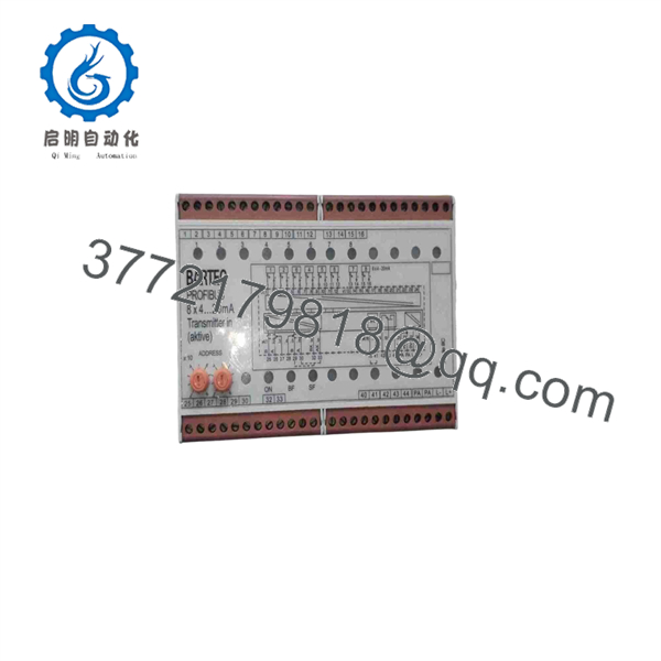
07-7331-23042000
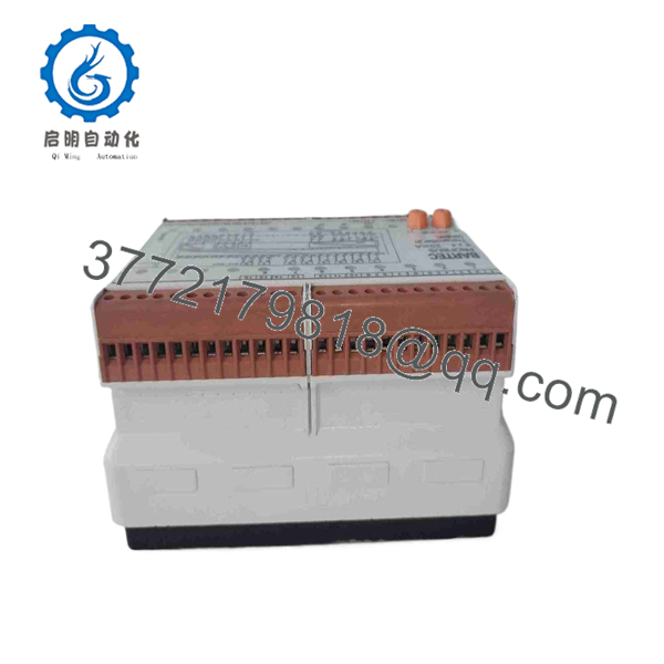
07-7331-23042000
Troubleshooting Quick Reference
| Symptom | Possible Cause | Relevance to this Part | Quick Check Method | Recommendation |
|---|---|---|---|---|
| SF (System Fault) LED lit, all channels down | Module internal fault or bus communication loss | ✅ High | Check PROFIBUS master diagnostics for the module’s station address | If master shows the station offline and wiring checks out, module likely needs replacement |
| BF (Bus Fault) LED lit | PROFIBUS cable fault, termination issue, or address conflict | ❌ Low | Check bus termination resistors and confirm no duplicate station addresses on segment | Usually a network/cabling issue, not the module |
| Single channel reads out of range or frozen | Field transmitter fault, wiring open/short at that channel | ❌ Low | Measure 4-20 mA loop directly at the transmitter terminals with a calibrated meter | Isolate the field loop before condemning the module |
| All channels show disconnection fault simultaneously | Module power supply fault | ✅ High | Check module supply voltage at input terminals | If supply is present and correct, module’s power stage may have failed |
| Module won’t respond to master polling at all | Wrong rotary switch address setting | ❌ Low | Verify rotary switch address matches the GSD/configuration in the PROFIBUS master | Reconfigure address before assuming hardware failure |
| Intermittent channel readings under vibration | Loose screw terminal connection | ❌ Low | Retorque field wiring terminals, inspect for corrosion | Usually a wiring fix, not a module fault |
If the fault isn’t isolated by these checks, send us the PROFIBUS diagnostic buffer from the master along with photos of the wiring terminals — that combination usually tells us whether it’s the module or the network.
Frequently Asked Questions (FAQ)
Is this an active or passive module — do I need to supply loop power?
This is a passive input design, meaning the field transmitters need their own loop power supply — the module doesn’t source 4-20 mA loop power itself. Confirm your transmitter wiring accounts for that before installation, or you’ll get flat-line readings that look like a module fault but aren’t.
Can I use this in a Zone 1 or Zone 2 hazardous area?
The Ex e (increased safety) protection concept covers specific zone and gas group ratings tied to the exact ATEX/IECEx certificate for your suffix. Don’t assume zone compatibility from the general MODEX family — pull the certificate number off your specific unit’s nameplate and check it against your site’s hazardous area classification before installing.
Does the coding switch need to be set before or after installation?
Set it before power-up. The PROFIBUS master won’t recognize the module correctly if the address is set after the network has already scanned the segment on startup — you’ll need to cycle power or force a re-scan either way, so save yourself the extra step.
Is this new production or an obsolete/legacy part?
Bartec’s MODEX line has had multiple generations over the years, and specific suffixes do get phased out in favor of updated variants. We’ll confirm current production status and, if it’s a legacy suffix, whether we’re supplying new-old-stock or tested surplus — we won’t represent an obsolete part as current production.
What testing do you run on a module like this before shipping?
Visual inspection for enclosure damage or corrosion, insulation resistance testing, and a functional bench test simulating PROFIBUS-DP communication and 4-20 mA input signals across all 8 channels, checking that diagnostics correctly flag simulated open-circuit and short-circuit conditions. Ask and we’ll provide the test report for your specific serial number.
Why does the part number matter so much for a module that looks physically identical to other MODEX units?
Because the digits in the middle of Bartec’s part numbers encode real functional differences — signal type, channel count, and sometimes protection concept — not just a batch or revision code. Two modules that look the same on the shelf can be wired for genuinely different input ranges. Match the full number, not just the visual housing, before you install it into a live loop.



