
 WhatsApp: +86 16626708626
 Email:
  Phone: +86 16626708626
Description
Key Technical Specifications
| Parameter | Value |
|---|---|
| Manufacturer | BARTEC |
| Model / Part Number | 07-7331-230H1010 |
| Product Family | ModEx |
| Product Type | PROFIBUS interface / analog I/O module |
| Communication Protocol | PROFIBUS |
| Analog Inputs | 4 × 4–20 mA |
| Analog Outputs | 4 × 4–20 mA |
| HART | Supported |
| Channel Count | 8 analog channels |
| Application | Ex / hazardous-area instrumentation |
| Typical System | Industrial process and oil & gas control systems |
| Supply | 24 VDC class; verify exact nameplate/current requirement |
| Part Number Variant | 07-7331-230H/1010 |
The slash-form designation 07-7331-230H/1010 is also used in supplier catalogs for the same part number. BARTEC-related product listings explicitly describe it as a PROFIBUS HART interface, while trade records describe the unit as a 4-port PROFIBUS interface with 24 V–500 mA and identify it as a replacement component for an automatic oil and gas drilling winch controller.
⚠️ Verification note: Publicly available sources do not provide a complete OEM datasheet for this exact variant. Do not treat unverified values for isolation, hazardous-area certification, temperature range, or current consumption as confirmed specifications.
Product Introduction
The BARTEC 07-7331-230H1010 is a ModEx PROFIBUS interface module designed for process instrumentation using 4–20 mA analog signals and HART communication. Catalog records identify its I/O arrangement as 4 analog inputs plus 4 analog outputs, with PROFIBUS providing the fieldbus connection to the higher-level control system.
This part is particularly relevant to legacy hazardous-area control installations where replacing the existing BARTEC module with a generic PROFIBUS I/O device would require engineering changes. Shipment records also identify the exact part as a replacement component for an ADS-10T automatic oil and gas drilling winch controller.
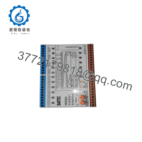
07-7331-230H1010
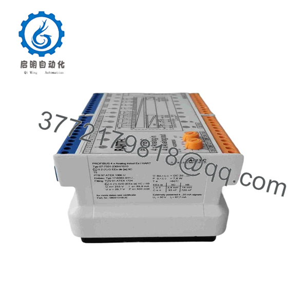
07-7331-230H1010
Installation & Configuration Guide
Stage 1: Pre-Installation Preparation — Approximately 10–15 minutes
⚠️ Safety First: This module is associated with Ex/hazardous-area instrumentation. Follow the site’s hazardous-area work permit, isolation, and LOTO procedures. Do not disconnect field wiring in a classified area unless the installation procedure explicitly permits it.
Tools Required:
- ESD wrist strap
- Digital multimeter
- Insulated screwdrivers
- Wire labels
- Smartphone/camera
- PROFIBUS diagnostic equipment, if available
Data Backup:
- Record the complete module number: 07-7331-230H1010.
- Photograph the existing module and terminal arrangement.
- Record the PROFIBUS station address.
- Document the PROFIBUS cable connections.
- Record every analog channel’s function.
- Identify which channels use HART communication.
- Photograph any rotary switches, DIP switches, or address selectors.
- Record the host PLC/DCS configuration.
❗ Do not assume channel assignments. An eight-channel module may be wired differently from one machine to another.
Stage 2: Removing the Old Module — Approximately 10 minutes
- Stop the affected process.
- Isolate the module’s 24 VDC supply.
- Apply LOTO according to site procedures.
- Verify the supply voltage is absent.
- Label each analog input and output.
- Photograph the terminal wiring.
- Disconnect the PROFIBUS connection.
- Disconnect field I/O wiring.
- Release the module from its mounting arrangement.
- Inspect terminals and connectors for corrosion, loose contacts, or damaged wiring.
⚠️ Do not interchange analog input and output wiring. A 4–20 mA input circuit and a 4–20 mA output circuit can look similar physically but perform completely different functions.
Stage 3: Installing the New Module — Approximately 10 minutes
- Verify the exact part number: 07-7331-230H1010.
- Compare the terminal layout against the removed module.
- Install the module in the same mounting position.
- Reconnect the PROFIBUS cable.
- Restore each analog input according to the original channel documentation.
- Restore each analog output.
- Verify shield and grounding arrangements.
- Confirm the module’s PROFIBUS address.
- Check the 24 VDC supply polarity.
- Inspect all terminals before energizing.
Configuration Clone — Crucial:
Verify:
- PROFIBUS station address
- GSD/device configuration
- Input channel assignments
- Output channel assignments
- 4–20 mA scaling
- HART channel configuration
- Diagnostic handling
- Fail-safe output behavior
⚠️ If the module is being installed in an existing PLC/DCS system, do not change the master configuration simply because the replacement module does not immediately communicate. First verify physical wiring, address, supply voltage, and the correct device description.
Stage 4: Power-On & Testing — Approximately 10–20 minutes
- Energize the 24 VDC supply.
- Observe module status indicators.
- Verify PROFIBUS communication.
- Check the slave/device diagnostic status.
- Verify each analog input with a calibrated 4–20 mA source.
- Verify each analog output using the plant’s approved test procedure.
- Confirm HART communication where applicable.
- Check engineering-unit scaling in the PLC/DCS.
- Test alarms and signal-failure diagnostics.
- Return the process to automatic control only after the I/O checks pass.
Recommended test sequence:
| Test | Expected Result |
|---|---|
| 24 VDC supply | Within specified operating range |
| PROFIBUS communication | No slave/device fault |
| AI channel at 4 mA | Correct low-scale value |
| AI channel at 12 mA | Correct mid-scale value |
| AI channel at 20 mA | Correct high-scale value |
| AO channel at low scale | Correct field current |
| AO channel at high scale | Correct field current |
| HART communication | Device data accessible where configured |
| PLC/DCS diagnostics | No unexpected module/channel fault |
Frequently Asked Questions (FAQ)
What is BARTEC 07-7331-230H1010?
It is a BARTEC ModEx PROFIBUS HART interface module used for analog process signals. Public catalog information identifies the configuration as 4 × 4–20 mA analog inputs plus 4 × 4–20 mA analog outputs.
Does the module support HART?
Yes. Product listings specifically identify the 07-7331-230H/1010 variant as a PROFIBUS HART module.
How many analog channels does it have?
The available catalog description specifies 8 analog channels: 4 analog inputs and 4 analog outputs, all associated with the 4–20 mA signal range.
Is 07-7331-230H1010 a PROFIBUS module?
Yes. Multiple independent product records identify the exact part number as a BARTEC PROFIBUS interface. Trade records further describe it as a four-port PROFIBUS interface and associate it with an automatic oil and gas drilling winch controller.
Is this module used in oil and gas equipment?
Yes. Shipment records specifically identify 07-7331-230H1010 as a replacement component for the controller of an ADS-10T automatic oil and gas drilling winch.
Can I replace it with another BARTEC 07-7331-230x module?
Not without checking the exact suffix. The 07-7331-230 family contains multiple variants, including modules for RTD inputs, other PROFIBUS configurations, and different I/O arrangements. BARTEC listings show several distinct variants under this family.
What should I verify before purchasing a replacement?
For a legacy replacement, verify 07-7331-230H1010, the physical terminal configuration, PROFIBUS address/configuration, 4–20 mA channel arrangement, HART requirement, hazardous-area certification, and nameplate information. Public sources confirm the basic PROFIBUS/HART and 4 × AI + 4 × AO configuration, but they do not provide enough primary documentation to safely infer every electrical and Ex parameter.



