
 WhatsApp: +86 16626708626
 Email:
  Phone: +86 16626708626
Description
Key Technical Specifications
| Parameter | Specification |
|---|---|
| Manufacturer | Basler AG |
| Model | A404k |
| Series | A400k |
| Sensor Type | Progressive-scan CMOS |
| Resolution | 2352 × 1726 pixels |
| Pixel Size | 7 µm × 7 µm |
| Maximum Frame Rate | 96 frames/s at full resolution |
| Video Interface | Camera Link Full |
| Video Output | 8 taps, 8-bit |
| Synchronization | External trigger or free-run |
| Exposure Control | Level-controlled or programmable |
| Power Supply | 12 VDC ±10% |
| Maximum Power | 7.2 W |
| Lens Mount | F-mount |
| Housing Size | Approximately 90 × 90 × 42 mm, excluding lens adapter |
| Weight | Up to approximately 615 g |
| Compliance | CE, FCC |
Basler’s A400k documentation identifies the A404k as a progressive-scan CMOS camera with 2,352 × 1,726 pixels and a maximum full-resolution frame rate of 96 frames/s. The A404k uses Camera Link Full with an 8-tap, 8-bit output configuration.
The manufacturer’s manual specifies a 12 VDC ±10% supply and maximum power consumption of 9.0 W for the A404k/A404kc configuration. A Basler A400k data sheet gives 7.2 W for the A404k, so power consumption should be checked against the exact camera revision and documentation supplied with the unit rather than treated as a universal value.
Product Introduction
The Basler A404k is a high-speed progressive-scan area-scan camera from the legacy A400k machine-vision family. It combines a 2,352 × 1,726 CMOS sensor with Camera Link Full output and a maximum full-resolution acquisition rate of 96 frames/s. This configuration is suited to inspection systems where deterministic, high-bandwidth image transfer is required.
The important selection point is the Camera Link Full interface. The A404k is not a GigE Vision or USB3 Vision camera, despite some current third-party listings that incorrectly assign those interfaces to the model. Basler’s own documentation specifies Camera Link and identifies the A404k/A404kc as using a second 26-pin MDR data connector for the higher-tap configuration.
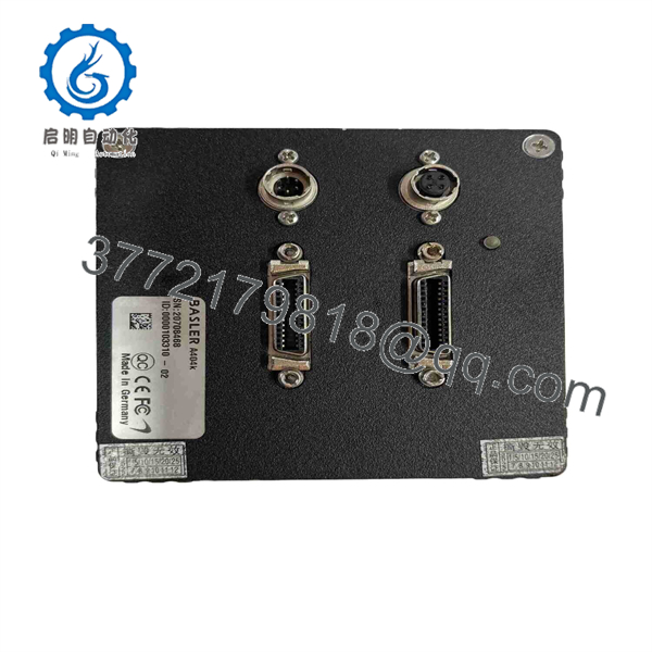
A404k
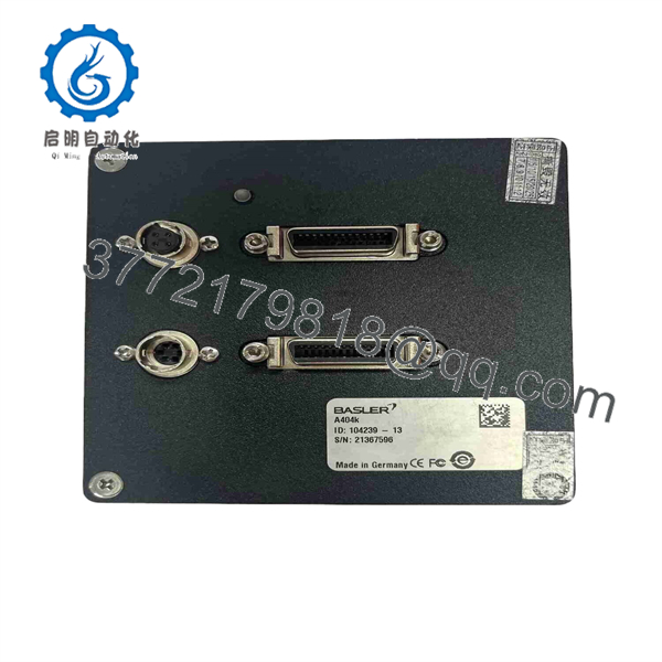
A404k
Installation & Configuration Guide
Stage 1 — Pre-Installation Preparation
- Confirm the camera label reads A404k and check whether the unit is monochrome or color.
- Verify that the installed frame grabber supports Camera Link Full and the A404k’s 8-tap configuration.
- Confirm the required Camera Link cables and MDR connectors.
- Verify the available power supply is within 12 VDC ±10%.
- Shut down the vision system and isolate associated machine power where required.
- Apply LOTO when camera replacement requires access to energized machine equipment.
- Protect the camera and frame grabber against ESD.
- Record the existing camera parameters, trigger configuration, exposure settings, gain/offset values, and acquisition software configuration.
- Photograph the cable routing and connector orientation before removal.
The A404k supports synchronization through an external ExSync/trigger signal or free-running operation, so the existing trigger architecture should be documented before replacement.
Stage 2 — Removing the Existing Camera
- Power down the camera and frame grabber.
- Disconnect the 12 VDC supply.
- Disconnect the Camera Link data cable(s).
- Disconnect the flash/trigger connection where installed.
- Release the camera mounting hardware.
- Remove the camera without stressing the lens mount or connector assembly.
- Inspect the Camera Link cable for bent contacts, damaged shielding, or mechanical wear.
- Check the mounting bracket for movement or distortion.
The Basler manual specifies a 26-pin female MDR connector for data, a 6-pin Hirose connector for power, and a 4-pin Hirose connector for flash triggering; A403k/A404k models additionally use a second 26-pin MDR data connector.
Stage 3 — Installing the Replacement
- Verify the replacement is A404k, not A402k or A403k.
- Confirm the camera’s sensor and color/monochrome configuration.
- Install the correct F-mount lens or existing compatible lens assembly.
- Mount the camera in the original mechanical position.
- Connect the Camera Link data cables.
- Connect the 12 VDC supply with correct polarity.
- Reconnect the trigger/flash wiring if used.
- Confirm that the camera optical axis has not shifted.
- Avoid applying mechanical force to the MDR or Hirose connectors.
- Confirm that the camera is adequately secured before starting acquisition.
Compatibility check
The A400k family contains several closely related models. The A404k differs from the A402k and A403k in maximum frame rate and Camera Link configuration. Basler documentation identifies the A404k as an 8-tap, Camera Link Full device, so a frame grabber designed only for a lower-tap Camera Link configuration may not provide a valid replacement path.
Stage 4 — Power-On & Testing
- Apply the specified DC supply.
- Confirm that the camera initializes normally.
- Open the machine-vision acquisition software.
- Verify camera communication through the frame grabber.
- Confirm the correct Camera Link tap configuration.
- Select the required image resolution.
- Restore the original trigger mode.
- Set exposure and gain parameters.
- Acquire a stationary test image.
- Verify image geometry and pixel integrity.
- Test acquisition at the intended frame rate.
- Run the conveyor or motion system and confirm that image timing remains synchronized.
- Perform a production-equivalent inspection cycle.
Troubleshooting sequence
If the camera does not acquire images, check:
- 12 VDC supply voltage and polarity
- Camera Link cable connection
- Frame-grabber compatibility
- Camera Link Full/tap configuration
- External trigger wiring
- Exposure timing
- Frame-grabber acquisition settings
- Lens and illumination
- Camera software configuration
If the image is corrupted rather than completely absent, inspect the Camera Link cable and tap configuration before replacing the camera. High-speed multi-tap Camera Link systems are sensitive to incorrect cable or frame-grabber configuration.
Frequently Asked Questions
Q1. What is the Basler A404k?
The A404k is a progressive-scan CMOS industrial area-scan camera in Basler’s A400k series. It provides 2,352 × 1,726-pixel images at up to 96 frames/s at full resolution.
Q2. What interface does the A404k use?
The A404k uses Camera Link Full with an 8-tap, 8-bit video output configuration. It is therefore important to distinguish it from later Basler cameras using GigE Vision, USB3 Vision, or other interfaces.
Q3. What power supply does A404k require?
Basler’s A400k manual specifies 12 VDC ±10%. The exact documented maximum power varies between Basler documents for the A404k/A404kc configuration, so the exact camera revision should be checked before sizing the power supply.
Q4. What is the maximum frame rate?
The A404k is specified for up to 96 frames/s at full resolution.
Q5. What lens mount does the A404k use?
The A404k is specified with an F-mount. The camera housing dimensions vary depending on whether the lens adapter is installed.
Q6. Can I replace an A404k with a newer Basler GigE camera?
Not as a direct electrical or software replacement. The A404k uses Camera Link Full, while many newer Basler cameras use different interfaces and configuration methods. A replacement would require checking the frame grabber, cabling, triggering, acquisition software, mechanical mounting, optical characteristics, and image-processing pipeline.
Q7. Is the A404k discontinued?
The A400k documentation is hosted by Basler under its discontinued cameras documentation, indicating that this is a legacy product family. For an existing production machine, retain the exact camera model and interface information when sourcing a spare rather than selecting a newer Basler camera solely by resolution.



