
 WhatsApp: +86 16626708626
 Email:
  Phone: +86 16626708626
Description
Key Technical Specifications
| Parameter | Value |
|---|---|
| Manufacturer | Basler Electric |
| Full Model | DECS-200N-C1 |
| Product Family | DECS-200N |
| Product Type | Compact negative-forcing digital excitation control system |
| Primary Application | Synchronous generator excitation and voltage regulation |
| Field-Output Variants | 63 V DC or 125 V DC; verify the actual unit label and application requirement |
| Continuous Field Current | Up to 20 A DC |
| Maximum Forcing Current | Up to 40 A DC |
| Negative Forcing Capability | Yes; active negative field forcing for fast field-current reduction |
| Continuous Field Voltage | 63 V DC or 125 V DC, variant dependent |
| Maximum Positive Forcing Voltage | 120–130 V DC on 63 V version; 240 V DC on 125 V version |
| Maximum Negative Forcing Voltage | −100 to −105 V DC on 63 V version; −200 V DC on 125 V version |
| Minimum Field Resistance | 3.15 Ω for 63 V version; 6.25 Ω for 125 V version |
| Operating Excitation Power | 80–277 V AC, single- or three-phase; exact range depends on configuration |
| Auxiliary Power Options | 24/48 V DC, 125 V DC, 24 V AC, or 120 V AC; verify C1 unit nameplate and wiring diagram |
| Voltage Sensing | Single- or three-phase; reported sensing range options from 100–600 V AC |
| Current Sensing | 1 A or 5 A CT inputs for metering/control and cross-current compensation |
| Regulation Modes | AVR, field-current regulation, VAR control, and power-factor control |
| AVR Regulation Accuracy | ±0.25% reported |
| Configuration Interface | Front-panel HMI and Windows-based configuration software |
| Local Communication | Front-panel RS-232, ASCII, 19,200 baud reported |
| Remote Communication | RS-485 Modbus RTU, 1,200–19,200 baud reported |
| Environmental Rating | Panel/cabinet installation; verify enclosure and installation requirements |
| Lifecycle Status | Discontinued by manufacturer |
The Basler DECS-200N-C1 is listed as a discontinued compact negative-forcing digital excitation control system with 63 V DC and 125 V DC output variants. Available technical data reports up to 20 A DC continuous field output, 40 A forcing current, and both positive and negative forcing capability. Confirm the specific field-voltage version, auxiliary supply, input sensing, and terminal configuration from the exact DECS-200N-C1 nameplate before ordering or commissioning.
Product Introduction
Basler Electric DECS-200N-C1 is a compact digital excitation controller for synchronous generators that requires fast field build-up and controlled negative forcing. It regulates generator voltage through field-current control and supports AVR, manual field-current regulation, reactive-power control, power-factor control, protection limiters, monitoring, and communication functions.
Negative forcing sets this unit apart from basic AVRs. The controller can actively reduce field current during large disturbances, load rejection, or protective actions, helping the generator excitation system respond faster. This is a configured generator-control device; match the field voltage, field resistance, sensing circuits, CT/PT ratios, and site parameter file before replacement.
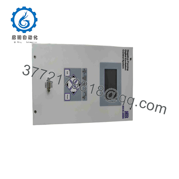
DECS-200N-C1
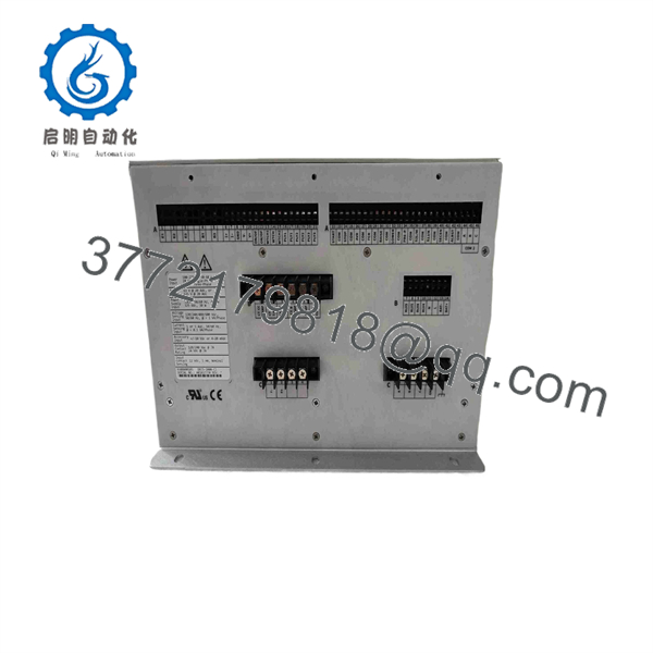
DECS-200N-C1
Troubleshooting Quick Reference
| Symptom | Possible Cause | Relevance to This Part | Quick Check Method | Recommendation |
|---|---|---|---|---|
| Controller display is blank | Missing auxiliary AC/DC supply, blown fuse, incorrect supply selection, reversed DC polarity, loose terminal, or failed controller | ✅ High | Use the exact wiring diagram for the installed unit. Measure the auxiliary supply at the DECS input terminals and confirm it falls within the nameplate rating. | Verify supply source, fuses, polarity, ground reference, and terminal torque before replacing the controller. |
| Generator voltage will not build | Field breaker open, no residual magnetism, open field circuit, failed rotating rectifier, no voltage sensing, blocked AVR mode, incorrect configuration, or failed output stage | ✅ High | Confirm generator speed and frequency, sensing voltage at the DECS terminals, field-breaker status, field continuity, and field current. Follow the approved commissioning procedure. | Rule out generator and exciter faults first. Do not apply manual excitation or field flashing without the OEM-approved method. |
| Generator voltage rises too high | Incorrect PT ratio, sensing leads landed on wrong phases, blown or loose sensing reference, reverse control action, wrong setpoint, manual-mode output, or failed field-control stage | ✅ High | Move the generator to a safe condition immediately. Compare DECS displayed voltage with a calibrated meter at generator terminals. Verify sensing phase connections and configured PT ratio. | Do not leave a generator online with uncontrolled voltage. Correct sensing and configuration errors before returning to service. |
| Generator voltage remains low | Underfrequency limiter active, maximum field-current limit reached, low prime-mover speed, open field connection, incorrect voltage reference, sensing ratio error, or exciter defect | ✅ High | Compare terminal voltage, generator frequency, field voltage, field current, and active limiter status. Inspect PT fuses and field connections. | Correct speed, sensing, field-circuit, or limiter issues before replacing DECS-200N-C1. |
| Field current goes to maximum | Loss of voltage sensing, PT fuse open, AVR control selected with invalid feedback, control polarity error, wrong configuration, or failed power stage | ✅ High | Check active alarm messages and measure sensing voltage directly at configured DECS terminals. Compare field-current command to measured current. | Remove the machine from service safely and diagnose. Maximum excitation can overheat the field system. |
| Generator has slow voltage recovery after a load change | Negative forcing disabled or misconfigured, forcing limits incorrect, field circuit resistance too high, weak exciter, limiter active, or controller issue | ✅ Medium | Retrieve event records and compare voltage, frequency, field current, and forcing response during the disturbance. Verify forcing parameters against approved settings. | Do not raise forcing values blindly. Confirm field winding limits and generator OEM data before changing response settings. |
| Generator voltage collapses too quickly during load rejection | Negative forcing set too aggressively, unstable tuning, sensing issue, field discharge path issue, or abnormal generator/exciter condition | ✅ Medium | Review oscillography and sequence-of-events data. Compare excitation current decay with the approved commissioning record. | Have qualified generator-control personnel review forcing and stability settings before returning the unit to parallel operation. |
| Reactive load sharing is incorrect | CT polarity reversed, CT ratio wrong, cross-current compensation wiring fault, wrong VAR/PF mode, incorrect settings, or incorrect parallel-control interface | ✅ Medium | Check CT secondary wiring, polarity marks, CT ratio settings, generator kVAr, power factor, and selected control mode. | Correct CT polarity and ratios first. A reversed CT can cause unstable reactive sharing and repeated protection actions. |
| Unit alarms on sensing loss | Open PT fuse, wiring fault, wrong sensing configuration, loose terminal, phase loss, or damaged voltage-input circuit | ✅ Medium | Measure configured phase-to-phase or phase-to-neutral voltage at the DECS sensing terminals. Inspect PT fuses and test continuity with power isolated. | Repair the sensing circuit before replacing the AVR. |
| RS-485 Modbus communication fails | Wrong RS-485 polarity, duplicate slave address, baud/parity mismatch, termination problem, missing communication option, or damaged cable | ❌ Low to Medium | Verify A/B terminals, shield grounding, slave address, baud rate, parity, stop bits, and end-of-line termination. Use a known-good USB-to-RS-485 adapter if needed. | Confirm the installed unit actually has the required remote-communication configuration before replacing hardware. |
| Controller trips after replacement | Wrong 63 V/125 V field version, incorrect sensing setup, incompatible firmware, missing configuration file, CT/PT mismatch, or wiring landed by memory | ✅ High | Compare old and replacement nameplates, wiring photos, terminal diagrams, firmware, and complete parameter files. Validate settings offline before energizing field power. | Stop and complete a documented commissioning check. Do not use defaults on a production generator. |
❗ Negative forcing is not a setting to “turn up until it feels better.” The -C1 can actively apply reverse field voltage to reduce excitation current quickly. Available data lists negative forcing down to approximately −100 to −105 V DC on 63 V systems and −200 V DC on 125 V systems. Incorrect forcing settings can stress field insulation, rotating-exciter components, and mechanical prime-mover systems.
❗ Record the exact controller configuration before removal. Save the parameter file and collect PT ratio, CT ratio, sensing topology, generator voltage rating, frequency, field voltage/current, limiter settings, stability values, AVR/FCR/VAR/PF settings, communication settings, event records, and firmware revision.
❗ Never wire from memory. A CT polarity reversal or sensing-phase error may produce a controller that looks alive on the panel but drives the generator incorrectly during parallel operation. Take terminal photos before removal and check the OEM wiring drawing line by line.
❗ Verify field resistance before selecting a replacement. The reported minimum field resistance is 3.15 Ω for the 63 V unit and 6.25 Ω for the 125 V unit. Measure the field circuit using the approved generator maintenance procedure, including cables and applicable brushes or rotating-exciter path. Do not select an output version only by the generator nameplate voltage.
If diagnosis remains unclear, provide technical supporll nameplate photos, generator and exciter data plates, excitation schematic, PT/CT wiring photos, measured terminal voltage and frequency, field-current readings, alarm text, event/oscillography records, and the exported configuration file.
Frequently Asked Questions (FAQ)
Whaer ?
er is a compact negative-forcing digital excitation control system for synchronous generators. It regulates generator terminal voltage by controlling the field circuit and supports AVR, manual field-current regulation, reactive-power control, power-factor control, limiting, protection, event recording, and communications.
What is the difference between DECS-200 and ?
The “N” identifies the negative-forcing version. A standard excitation controller can increase field current quickly, but can also actively drive field current down using controlled negative output voltage. This helps the excitation system respond more quickly after disturbances, large load changes, fault clearing, and load rejection. Available comparison material states that provides greater output and forcing capability than DECS-200.
That capability requires correct commissioning. It is useful only when field ratings, forcing limits, generator dynamics, and protection settings have been engineered together.
Is obsolete?
s. is listed as discontinued by the manufacturer. Basler’s current replacement family includes the DECS-250N, which provides negative-forcing excitation control and generator or motor protection functions.
For an emergency spare, an eed is usually less disruptive than a platform conversion. For a planned modernization, assess DECS-250N as an engineered retrofit that includes wiring, parameter conversion, sensing/CT/PT validation, panel fitment, factory acceptance testing, and generator commissioning.
What field-output ratings does it support?
Published product information lists 63 V DC and 125 V DC output variants, up to 20 A DC continuous output, and up to 40 A forcing current. The available output voltage and minimum field resistance differ by variant:
| Output Version | Continuous Field Voltage | Maximum Positive Forcing | Maximum Negative Forcing | Minimum Field Resistance |
|---|---|---|---|---|
| 63 V DC | 63 V DC | 120–130 V DC | −100 to −105 V DC | 3.15 Ω |
| 125 V DC | 125 V DC | 240 V DC | −200 V DC | 6.25 Ω |
These values come from a secondary technical source and must be verified against the exact controller label and Basler documentation before field connection.
Can a with a generic AVR?
No. A generic AVR is not a direct replacement for a negative-forcing digital excitatm. handles regulated field output, positive and negative forcing, PT/CT sensing, VAR/PF control, limiters, protection logic, communication, alarms, and parallel-operation behavior.
Replacing it with a basic AVR without reengineering can cause unstable voltage control, reactive-load-sharing failure, incorrect protection response, field overcurrent, or generator damage. Use an exact spare for outage repair or execute a documented modernization project.
Will the old configuration transfer to a replacement unit?
Not automatically. You must export the configuration from the installed controller and confirm that the replacement has compatible hardware and firmware. Then compare every parameter before download.
Document these items before removal:
- Generator nominal voltage and frequency
- PT ratio, CT ratio, and sensing topology
- Field nominal voltage, field current, and measured field resistance
- AVR setpoint and control action
- Manual/FCR settings and output limits
- VAR/PF control settings and reactive load-sharing setup
- Underfrequency, V/Hz, stator-current, minimum-excitation, and maximum-excitation limits
- Stability settings and forcing limits
- Alarm, trip, input, and output assignments
- RS-232 and RS-485 settings, Modbus address, baud rate, and parity
- Firmware revision, event history, and oscillography settings
A default configuration is not safe for a production generator.
Canap ?
No. Never hot-swap an excitation control system. It manages generator field energy and can affect terminal voltage, reactive power, protection logic, and breaker operations. Removing it energized can cause uncontrolled voltage, a generator trip, arc damage, or injury.
Coordinate the outage with operations. Place the generator in an approved safe state, isolate auxiliary power, sensing circuits, and field circuits as required, discharge stored energy, verify absence of voltage, then use proper ESD precautions during replacement.
Why is my generator voltage unser replacement?
Start with configuration and sensing—not the assumption that the replacement is defective. Most post-swap instability comes from one of these:
- Incorrect PT ratio or sensing-phase wiring
- Reversed CT polarity
- Wrong field-voltage variant or incorrect field-circuit connection
- Default stability or forcing parameters
- Missing or incompatible parameter file
- Different firmware behavior
- Loose sensing or field terminals
- Generator operating outside the assumed load range
Retrieve the controller event record, compare terminal-voltage readings with displayed values, verify field current, and review the configured stability and forcing values against the pre-replacement record.
What condition should I buy: New Surplus or Refurbished?
Choose based on proof of identity and functional testing:
- New Original / New Surplus: Unused legacy inventory. Request actual nameplate, serial-number, connector, packaging, and storage-condition photos.
- Refurbished (tested): Previously used unit that has passed a documented bench test. Request sensing, field-output, negative-forcing, communication, and sustained-load test results.
- Used, untested: Highest risk. Do not use it as the sole outage spare for a critical generator.
For excitation equipment, a supplier that can document a controlled field-load test is more credible than one that only confirms the display powers up.
What testing should a supplier perform before shipping?
Request a documented test foct serial-numbered unit:
- Verify full model number, serial number, voltage variant, firmware, terminal layout, and configuration-access status
- Inspect the enclosure, front display, keypad, heatsink, terminal blocks, connectors, mounting points, and internal areas visible without destructive disassembly
- Power up with the correct auxiliary AC or DC supply
- Test display, keypad, local alarms, control-mode selection, and configuration-menu access
- Simulate single- or three-phase PT sensing at the correct scaled voltage
- Simulate CT inputs where the test fixture supports VAR/PF functions
- Drive a properly rated resistive or electronic field-load bank at controlled output levels
- Verify positive output, controlled negative forcing, output-current limiting, and stable regulation response
- Test RS-232 and RS-485 Modbus RTU communication where installed
- Run a sustained-load thermal test while monitoring output current and alarms
- Provide a dated QC report, test photos or video, and ESD-safe packaging
or , “powers on” is not a meaningful acceptance test. The supplier should demonstrate sensing, excitation output, negative forcing, parameter access, and stable loaded operation.



