
 WhatsApp: +86 16626708626
 Email:
  Phone: +86 16626708626
Description
Key Technical Specifications
| Parameter | Value |
|---|---|
| Manufacturer | Beckhoff Automation |
| Model / Part Number | CX1100-0001 |
| System Compatibility | CX1010, CX1020, CX1030 CPU Modules |
| Input Power Voltage | 24 V DC (-15% / +20%) |
| I/O Bus Interface | K-Bus (Beckhoff Bus Terminals KL/KS Series) |
| Max Power Output | 1.7 A to system bus (5 V DC) |
| Display Unit | LC display, 2 lines x 16 characters, illuminated |
| User Interface | 4-way selector switch with press button |
| Diagnostics | Diagnostic LEDs for Power (PWR), K-Bus status, and system alerts |
| Operating Temperature | 0 °C to +55 °C (32 °F to 131 °F) |
| Enclosure Rating / Mounting | IP20 / 35 mm DIN Rail |
Product Introduction & Application Context
The Beckhoff CX1100-0001 is a specialized power supply and bus coupling module designed for Beckhoff CX Embedded Industrial PCs. It mounts alongside CX series CPUs to step down and regulate the cabinet’s 24 V DC power supply for the CPU and local I/O slice bus.
Equipped with an integrated K-Bus interface, the CX1100-0001 enables direct attachment of standard Beckhoff KL/KS Series Bus Terminals to the CPU without additional couplers. Its built-in 2×16 LCD screen and 4-way navigation switch allow engineers to read system statuses, IP configurations, and diagnostic error codes directly on the control cabinet door without attaching a screen or diagnostic laptop.
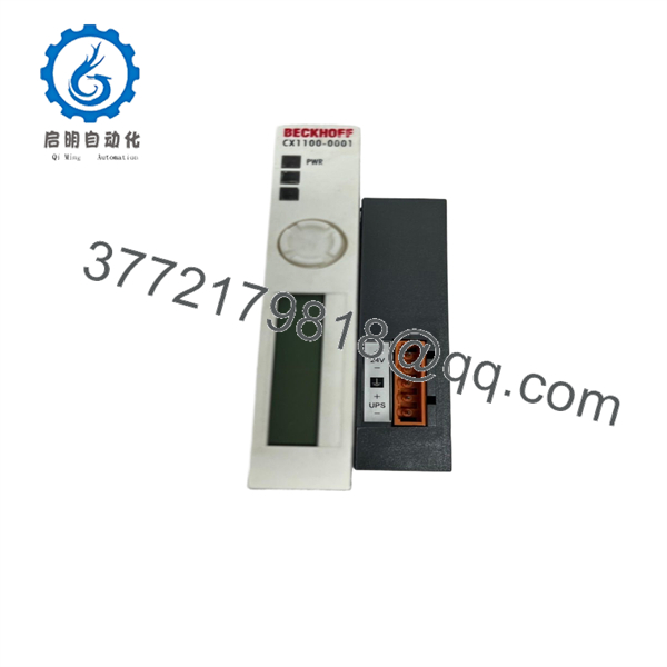
CX1100-0001
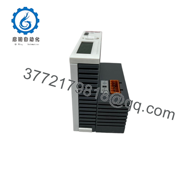
CX1100-0001
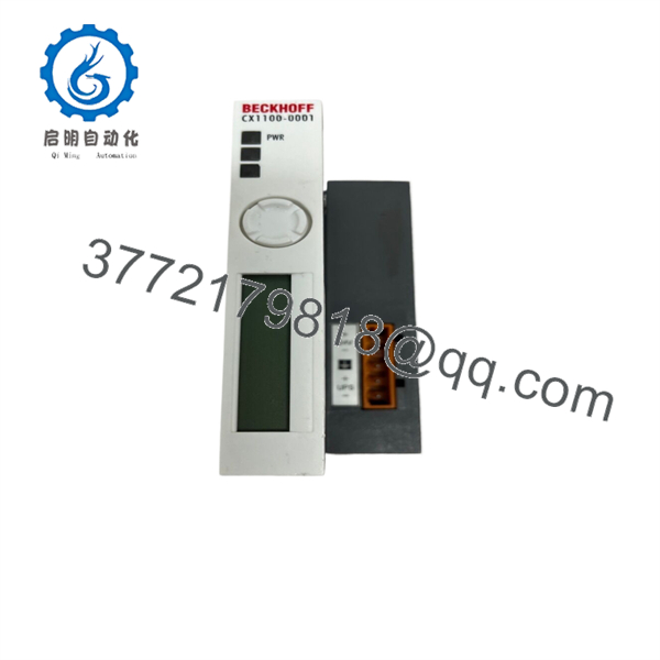
CX1100-0001
Replacement & Installation Procedure
1
Stage 1: Isolation & Wiring Documentation
Safety & LOTO
1.Stage 1: Isolation & Wiring Documentation:Safety & LOTO.
Disconnect main cabinet power and implement Lock-Out/Tag-Out (LOTO). Use a digital multimeter to confirm zero potential on the 24 V DC terminal block. Label all incoming power leads and attached K-Bus terminal slices before disassembly.
Verification: Multi-meter shows 0.0 V DC across the power terminals.
2
Stage 2: Module Removal and Attachment
Physical Swap
2.Stage 2: Module Removal and Attachment:Physical Swap.
Release the interlocking rail clips between the CX CPU module and CX1100-0001. Slide the unit sideways to release it from the system bus connector, then unclip it from the 35 mm DIN rail. Snap the new CX1100-0001 onto the rail and slide it securely onto the CPU module side pins.
Verification: Mechanical interlocks lock together firmly with no gap between housings.
3
Stage 3: Wiring Reconnection & Power-Up
System Power-On
3.Stage 3: Wiring Reconnection & Power-Up:System Power-On.
Reinsert the 24 V DC power plug into the orange terminal header. Re-apply system power and monitor the front-panel initialization sequence.
Verification: The green PWR LED illuminates steadily and the LC display initializes showing system runtime messages (e.g., TwinCAT / System IP).
System Compatibility & Operating Notes
- I/O Bus Selection: The supports Beckhoff K-Bus slices. If your application relies on EtherCAT Terminal slices (EL/ES Series), a CX1100-0004 or CX1100-0002 EtherCAT coupler variant is required instead.
- TwinCAT System Integration: No specific driver download is required; the module’s power management and bus logic are automatically detected by TwinCAT System Manager during hardware scan.
- Display Configuration: Custom text strings, IP address parameters, or system error messages can be routed to the LCD display via TwinCAT system functions in PLC code.
Frequently Asked Questions (FAQ)
What is the difference between and CX1100-0004?
The integrates a K-Bus interface for standard KL-series terminals. The CX1100-0004 features an E-bus (EtherCAT) interface designed for EL-series EtherCAT terminals.
Can I replace a with power turned on?
No. Hot-swapping power supply modules can damage internal communication lines or trigger unexpected field I/O state changes. Always isolate 24 V DC power before servicing.
What does it mean if the PWR LED on the is off?
An unlit PWR LED indicates either an absence of 24 V DC supply voltage, reverse polarity wiring on the input header, or an internal thermal fuse tripping due to an excessive current load on the 5 V system bus.
Does this module require a battery or memory card?
No. The acts purely as a power supply and interface coupler; memory cards and battery backups are situated directly within the main CX CPU module.



