
 WhatsApp: +86 16626708626
 Email:
  Phone: +86 16626708626
Description
Key Technical Specifications
- Manufacturer: Beijer Electronics
- Model: CIMREX-67
- Part Number: 04401B
- Product Type: Graphic operator terminal / HMI panel
- Display Size: 5.7 inches
- Power Supply: 24 V DC
- Maximum Current Draw: 400 mA
- Nominal Power Requirement: Up to 9.6 W at 24 V DC
- Panel Cutout: 188 × 139 mm
- Programming Platform: Beijer Information Designer
- Primary Application: Legacy PLC machine control and process operator interface
- Replacement Direction: Beijer X2 pro 7, subject to project conversion, mounting adaptation, communications validation, and function review
- Migration Hardware: Beijer adapter plate options 100-1069, 100-1065, or 100-1066 may apply for CIMREX 67-to-X2 pro 7 conversions
- Product Lifecycle: Legacy / discontinued; confirm actual stock, display condition, and communication-port configuration before purchase
Beijer’s official migration table identifies the CIMREX 67 as the counterpart to the E610 and lists X2 pro 7 as the current migration direction. The existing CIMREX 67 cutout is 188 × 139 mm, while the X2 pro 7 cutout is 189 × 128 mm, so an adapter plate or enclosure modification may be required. Third-party inventory listings identify 04401B as a 24 V DC, 400 mA CIMREX 67 HMI panel.
Product Introduction
The Beijer CIMREX-67 04401B is a 5.7-inch legacy graphic HMI operator panel used to display process data, accept operator commands, manage alarms, and communicate with a connected PLC or controller. It is commonly installed in machinery, packaging systems, utility skids, and small process-control cabinets built around Beijer CIMREX or E600-generation projects.
The main reason to source a CIMREX-67 is to restore an existing machine without immediately converting its HMI application. It is a like-for-like legacy spare, not a modern platform upgrade. For long-term support, Beijer directs CIMREX 67 users toward the X2 pro 7, but project conversion must address physical cutout, communication drivers, and any original function-button or indicator usage.
Installation & Configuration Guide
Stage 1: Pre-Installation Preparation — 10 minutes
- ⚠️ Safety first: Notify operations, stop the machine or process, verify a safe state, apply lockout/tagout, and isolate the 24 V DC HMI supply. Wait at least 5 minutes before removing the panel.
- Confirm the replacement label reads Beijer CIMREX-67 04401B. Do not assume another CIMREX model is interchangeable because the front dimensions appear similar.
- Prepare:
- Grounded ESD wrist strap
- PH1 screwdriver
- Digital multimeter
- Wire labels
- Smartphone for photographs
- Approved panel drawing and PLC/HMI communication drawing
- Back up the existing CIMREX project from the panel or engineering workstation if the panel remains operational. Use the correct version of Beijer Information Designer for the installed project.
- Record:
- PLC make, model, and firmware
- Communication-driver selection
- Serial-port settings: baud rate, parity, data bits, stop bits, station number
- Any network address where an Ethernet option is installed
- HMI firmware and project version, if displayed in system information
- Photograph the rear terminal block, communication ports, shield grounding, power-supply polarity, and panel mounting hardware.
⚠️ Critical: A replacement panel may power up correctly but fail to communicate if its loaded project uses the wrong controller driver or serial settings. Back up before you pull the old terminal.
Stage 2: Removing the Old Panel — 5 minutes
- Remove the cabinet door or rear protective cover as required for access.
- Use a multimeter to verify that the 24 V DC supply at the HMI power terminals is de-energized.
- Label the 24 V DC positive, 0 V, protective-earth, serial, and network conductors.
- Disconnect the power plug and communication cable without pulling on the cable jacket.
- Release the panel’s mounting clips or rear clamps. Hold the front of the HMI during removal; older plastic bezels can crack when unsupported.
- Pull the CIMREX-67 straight out from the front of the enclosure.
- Inspect the 188 × 139 mm cutout, panel gasket surface, cable strain relief, and communication connector for damage or contamination.
⚠️ Note: Retain the old panel until the replacement has booted, communicated with the PLC, and completed an operator acceptance check.
Stage 3: Installing the New Module — 10 minutes
- Put on the grounded ESD wrist strap and remove the replacement HMI from its antistatic packaging.
- Check the model number, power rating, connector arrangement, and rear-label revision against the removed panel.
- Install the front gasket correctly. A damaged or pinched gasket can allow cabinet dust or moisture to reach the display and touchscreen assembly.
- Insert the CIMREX-67 evenly into the existing panel cutout.
- Fit the mounting clips or clamps and tighten evenly. Do not overtighten; excessive force can distort the bezel or damage the display assembly.
- Reconnect the 24 V DC supply, observing polarity exactly.
- Reconnect the PLC communication cable and restore shield grounding exactly as documented.
- If the panel did not arrive preloaded with the correct application, download the archived project using the approved Information Designer software and correct transfer cable.
Self-checklist:
- Model label confirms 04401B
- 24 V DC polarity is correct
- Panel gasket is seated and undamaged
- Communication cable matches the original port and pinout
- Shield connection matches the cabinet drawing
- Mounting clips are secure without bezel distortion
- Correct HMI project is loaded
Stage 4: Power-On and Testing — 10 to 20 minutes
- Before energizing, measure the HMI supply at the terminal block. Confirm correct 24 V DC polarity and no short circuit between 24 V and 0 V.
- Energize the 24 V DC control supply.
- Verify that the starts normally and that the display initializes without backlight flicker, horizontal lines, or a blank screen.
- Confirm that the expected application loads rather than an empty, default, or incorrect project.
- Verify controller communications:
- Check live tags and displayed values.
- Command only approved noncritical test functions.
- Confirm alarms update correctly.
- Confirm that numeric entry, navigation keys, and touchscreen areas respond as expected.
- Test the communication link under normal operating conditions. Serial settings must match the connected PLC exactly.
- Restore machine control to operations only after the operator confirms that all required pages, alarms, setpoints, and commands work correctly.
⚠️ Troubleshooting note: If the panel powers up but shows no live PLC values, do not immediately condemn the HMI. First verify the loaded project, PLC driver, communication port, station address, cable pinout, baud rate, parity, and serial-cable shield arrangement. On older HMI installations, one incorrect parity setting is enough to create a complete communication failure.
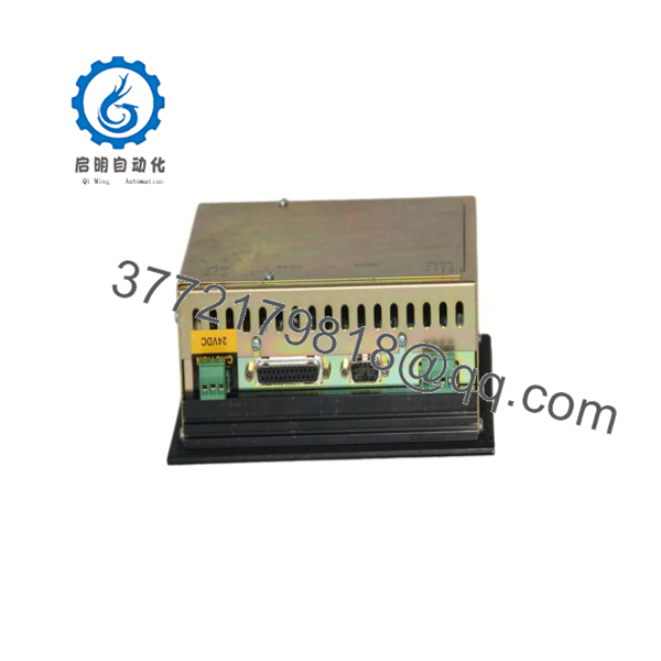
CIMREX-67 04401B
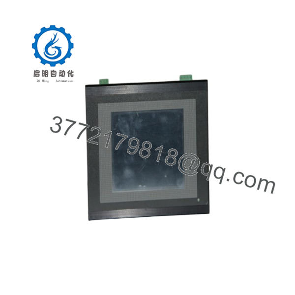
CIMREX-67 04401B
Frequently Asked Questions
Can I hot-swap the while powered?
No. Isolate the 24 V DC supply before removing or connecting the panel. The is not a hot-swappable device. Pulling the power connector under load can damage the connector, interrupt PLC communications, and create uncontrolled operator-interface behavior during machine operation.
Is the 04401B obsolete?
Yes. It is a legacy CIMREX-generation HMI, and availability is generally limited to New Surplus, tested used, or refurbished inventory. Beijer’s official migration information directs CIMREX 67 applications toward the X2 pro 7 platform.
What is the current replacement for 04401B?
The Beijer X2 pro 7 is the designated migration direction, but it is not a direct plug-and-play electrical replacement. The original CIMREX 67 panel cutout is 188 × 139 mm, compared with 189 × 128 mm for the X2 pro 7. Beijer lists adapter plate options for this migration, but you must still convert the project, validate PLC communications, and review the original use of physical function buttons and LEDs.
Will I lose the HMI application when I remove the old panel?
You can lose access to it if the project exists only in the panel and the old panel has already failed. The application is stored in the HMI’s nonvolatile memory, but legacy upload capability depends on the project, software version, transfer method, and panel condition. Back up the application before replacement whenever possible.
Honestly, this is where many legacy-panel replacements become difficult. A physically identical spare is easy; rebuilding undocumented alarm pages, recipes, passwords, and screen navigation is not.
Can I use a used as a replacement?
Yes, but inspect it carefully. Request actual photos showing the front overlay, display condition, rear label, connectors, mounting hardware, and power terminals. Require confirmation that it boots, retains a project, accepts touchscreen or keypad inputs, and communicates on its required port. A used panel with screen burn-in, failed backlight, damaged overlay, or weak internal battery may create more downtime than it saves.
Why does the replacement panel power up but not communicate with the PLC?
The most common causes are an incorrect application file, incompatible PLC driver, wrong serial settings, incorrect station address, incorrect cable type, or a loose communication connector. Do not wire from memory. Compare every pin and setting against the old panel, PLC program documentation, and approved machine drawings.
Why might a New Surplus cost less than an OEM migration project?
A New Surplus panel typically comes from excess inventory, discontinued-project stock, or unused spares. The lower price reflects its legacy status and limited future support, not necessarily a defect. A full migration to an X2 pro 7 costs more because it can require a new HMI application, communications testing, enclosure work, adapter hardware, site commissioning, and operator acceptance testing.



