
 WhatsApp: +86 16626708626
 Email:
  Phone: +86 16626708626
Description
Key Technical Specifications
| Parameter | Value |
|---|---|
| Manufacturer | BENDER |
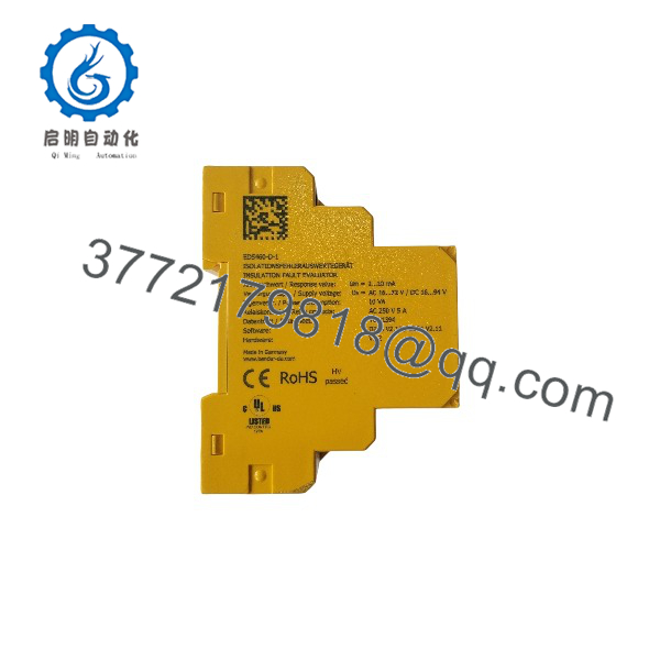
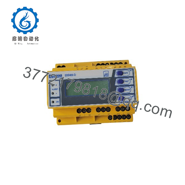
| Model | EDS460-D-1 |
| Series | ISOSCAN EDS460 |
| Article Number | B 9108 0001 |
| Product Type | Insulation fault locator |
| Application | Unearthed AC, AC/DC, and DC IT systems |
| EDS Response Range | 2–10 mA |
| RCM Measuring Range | 100 mA–10 A |
| Measuring Channels | 12 |
| Maximum Measuring Channels | Up to 1,080 with system expansion |
| AC Supply | 16–72 V, 42–460 Hz |
| DC Supply | 16–94 V |
| Measuring Transformers | BENDER W, WR, or WS series |
| Display | Backlit graphical LC display |
| History Memory | 300 records |
| Alarm Relays | 2 × changeover contacts |
| Response Delay | 0–24 s |
| Release Delay | 0–24 s |
| Operating Temperature | −25 to +55 °C |
| Mounting | DIN rail according to IEC 60715 or 2 × M4 screw mounting |
| Terminal Protection | IP20 |
| Housing | Polycarbonate, UL94 V-0 |
| Weight | ≤360 g |
| Terminal Torque | 0.5–0.6 Nm |
BENDER’s current technical documentation specifies screw-terminal connections, IEC 60715 DIN-rail mounting, ≤360 g weight for the EDS460 family, and 0.5–0.6 Nm terminal tightening torque.
Critical compatibility point: EDS460-D-1 is not simply a generic insulation monitor. It works with external measuring current transformers and belongs to BENDER’s EDS architecture. The applicable W/WR/WS measuring transformer, wiring, system voltage, response threshold, and alarm configuration must match the installation.
Product Introduction
The BENDER EDS460-D-1 is an ISOSCAN insulation fault locator for unearthed AC, AC/DC, and DC IT systems. It evaluates insulation-fault signals from external measuring current transformers and provides 12 measuring channels, a graphical LC display, and two common alarm relay outputs. Its supply range is 16–94 VDC or 16–72 VAC at 42–460 Hz.
The unit combines insulation-fault location with residual-current measurement, covering 2–10 mA for the EDS function and 100 mA–10 A for RCM measurement. For replacement work, the external measuring transformers and existing EDS wiring are just as important as the EDS460-D-1 part number.
EDS460-D-1
EDS460-D-1
Installation & Configuration Guide
Stage 1: Pre-Installation Preparation — Approximately 10 Minutes
⚠️ Safety First
- Notify operations and establish the approved maintenance window.
- Put the monitored electrical system into the required safe condition.
- Apply lockout/tagout to the applicable supply before disconnecting the -D-1.
- Verify the supply terminals are de-energized with a properly rated multimeter.
- Wait for stored energy to discharge according to the site’s electrical safety procedure.
- Confirm that the replacement is specifically -D-1 / B 9108 0001.
Tools Required
- Properly rated multimeter
- ESD wrist strap
- Insulated screwdriver
- Wire labels
- Smartphone or camera
- Torque screwdriver capable of 0.5–0.6 Nm
Data Backup
- Photograph the complete front and terminal arrangement.
- Photograph all connected measuring-transformer wiring.
- Record the existing EDS response settings.
- Record alarm relay configuration and delay settings.
- Record the connected measuring transformer types.
- Photograph the current display configuration and any programmed parameters.
- Record the unit’s article number and hardware identification.
⚠️ Do not change measuring-transformer wiring during a s replacement. The locator depends on the external measuring-current-transformer arrangement. BENDER specifies W, WR, and WS series transformers for this architecture.
Stage 2: Removing the Old Module — Approximately 5 Minutes
- Confirm the equipment is isolated and electrically safe.
- Photograph the terminal blocks before disconnecting anything.
- Label every conductor individually.
- Disconnect the supply wiring.
- Disconnect the measuring-transformer connections.
- Disconnect alarm relay wiring if installed.
- Release the DIN-rail retaining mechanism.
- Remov from the rail.
- Inspect the wiring and terminals for overheating, corrosion, or loose conductors.
- Inspect the DIN rail and enclosure for mechanical damage.
⚠️ Keep the original unit until commissioning is finished. If a parameter or terminal assignment is unclear, the removed device is your physical reference.
Stage 3: Installing the New Module — Approximately 10 Minutes
- Verify the replacement l, B 9108 0001.
- Confirm the supply voltage is compatible with the -D-1 version.
- Mount the unit on the DIN rail according to IEC 60715, or use the specified M4 mounting points.
- Connect the supply wiring according to the approved schematic.
- Reconnect the measuring-transformer circuits exactly as photographed.
- Reconnect the two alarm relay circuits where installed.
- Do not substitute the -D-2 version without checking the supply architecture.
- Tighten screw terminals to the specified 0.5–0.6 Nm.
- Check that no conductor is loose or trapped beneath an adjacent terminal.
- Confirm adequate enclosure clearance and that the unit can dissipate heat normally.
Self-Checklist
- confirmed
- B 9108 0001 confirmed
- Supply voltage verified
- Measuring-transformer wiring copied correctly
- Alarm relay wiring checked
- DIN rail locked
- Terminal torque verified
- No loose conductors
- Configuration documented
Stage 4: Power-On & Testing — Approximately 10–15 Minutes
- Perform a final wiring inspection before energizing.
- Apply the specified supply voltage.
- Confir boots normally.
- Verify the graphical LC display operates correctly.
- Check the connected measuring-transformer channels.
- Run the unit’s test function according to the BENDER operating procedure.
- Confirm the programmed response value.
- Verify the common alarm relay operation.
- Confirm the RCM measurement is reasonable for the monitored system.
- Check the insulation-fault location function using an approved test condition.
- Record the final settings and test results.
- Return the monitored system to normal operation only after the alarm and fault-location functions have passed testing.
⚠️ Troubleshooting Note: I powers up but cannot identify a measuring channel, check the measuring-transformer wiring and transformer type before replacing the locator. If the alarm relay behaves incorrectly, check the configured relay operating mode and delay settings. BENDER’s documentation provides separate configuration parameters for response and release delays.
Frequently Asked Questions (FAQ)
What is the B used for?
locates insulation faults in unearthed AC, AC/DC, and DC IT systems. It works with external measuring current transformers and identifies the affected circuit rather than merely indicating that an insulation problem exists.
What is the difference be and -D-2?
The main difference is the supply-voltage version.
- 16–94 VDC or 16–72 VAC, 42–460 Hz
- 70–276 V AC/DC, with the AC range specified at 42–460 Hz
Both belong to the family, but they are not interchangeable based only on physical appearance. Verify the cabinet supply before ordering.
include the measuring current transformers?
No is the evaluation/locating device. The measuring-current-transformer circuits are external. BENDER specifies compatible W, WR, and WS series measuring transformers for the architecture.
If you are replacing a complete insulation-fault detection system, check the transformer part numbers separately.
How many measuring channels support?
provides 12 measuring channels on the device. BENDER’s system documentation describes expansion to as many as 1,080 measuring channels, with scanning time dependent on the system configuration.
Do not confuse the 12 physical channels on one with the maximum channel count of a complete interconnected EDS system.
What are the EDS and RCM measurement ranges?
The EDS function uses a 2–10 mA response range, while the RCM function measures 100 mA–10 A. These functions serve different purposes: EDS is used for insulation-fault location, while RCM provides residual-current measurement.
Can I re with -L-1?
Not without checking the existing operator interface and configuration requirements. The D version uses a graphical LC display, while the L version uses a 7-segment display/LED indication. Both have the same general supply-voltage class, but the user interface and available indication differ.
For a maintenance replacement, match the exact installed model rather than assuming the same family number means equivalent functionality.
still available as new original stock?
The model and article number remain documented by BENDER, but actual physical stock condition depends on the supplier. BENDER’s current documentation still lists , article number B 9108 0001.
For procurement, require the seller to state the exact condition as Factory Sealed, New Original, New Surplus, or Refurbished/Tested. For a refurbished unit, request the test scope and warranty rather than accepting “tested” as a sufficient description.



