
 WhatsApp: +86 16626708626
 Email:
  Phone: +86 16626708626
Description
Key Technical Specifications
| Parameter | Value |
|---|---|
| Model | IRDH275B-435 |
| BENDER Article No. | B91065101 |
| Device Type | ISOMETER insulation monitoring device |
| System Voltage | AC 0–793 V; DC 0–650 V |
| Supply Voltage | AC 88–264 V; DC 77–286 V |
| Supply Frequency | 42–460 Hz for AC supply |
| Insulation Resistance Response Range | 1 kΩ–10 MΩ |
| Alarm Thresholds | Alarm 1 and Alarm 2, independently adjustable |
| Analog Output | 0(4)–20 mA, galvanically isolated |
| Serial Interface | RS-485 |
| Protocol | BMS |
| BMS Address | 1–30; factory setting 3 |
| RS-485 Cable Length | Up to 1,200 m |
| Terminating Resistor | 120 Ω, 0.5 W |
| Power Consumption | ≤14 VA |
| Operating Temperature | −10 to +55 °C |
| Storage Temperature | −40 to +70 °C |
| Mounting | DIN rail mounting / screw mounting option |
| Terminal Type | Screw terminals |
| Conductor Size | 0.2–4 mm² rigid; 0.2–2.5 mm² flexible |
| Terminal Torque | 0.5 Nm |
| Display | Two-line LC display |
| Applicable Standards | IEC 61557-8; IEC 61326-2-4; IEC 60664-1 |
The IRDH275B-435 is specifically the B-version with BMS communication, real-time-clock history memory, and a galvanically isolated 0(4)–20 mA output. The -435 suffix identifies the high-range auxiliary supply variant: AC 88–264 V or DC 77–286 V.
Product Introduction
The BENDER IRDH275B-435 is an ISOMETER insulation monitoring device for unearthed AC IT systems, including systems with galvanically connected rectifiers or converters, and for DC IT systems. It monitors insulation resistance up to 10 MΩ and provides two independently adjustable alarm thresholds.
The B-version adds an electrically isolated RS-485 BMS interface, real-time-clock history memory, and isolated 0(4)–20 mA output. The device can directly monitor systems up to 793 V AC or 650 V DC; higher system voltages require an appropriate BENDER coupling device.
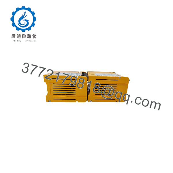
IRDH275B-435
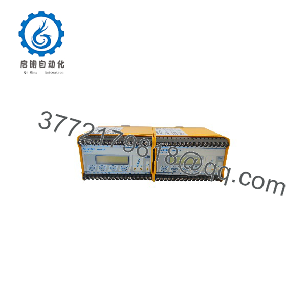
IRDH275B-435
Installation & Configuration Guide
Stage 1: Pre-Installation Preparation — Approximately 5–10 Minutes
⚠️ Safety First: This device connects directly to an electrical IT system. Have qualified electrical personnel perform the replacement. Notify operations, place the system in a safe state, apply lockout/tagout, and verify absence of hazardous voltage before touching wiring.
- Isolate the auxiliary supply and monitored circuit according to the plant’s electrical isolation procedure.
- Allow the equipment to discharge. A 5-minute waiting period is a practical minimum for associated equipment, but follow the site’s electrical safety procedure and the equipment manufacturer’s requirements.
- Prepare an ESD wrist strap, PH1 screwdriver, multimeter, wire labels, and smartphone/camera.
- Photograph the complete front panel and every terminal connection.
- Record the existing:
- BMS address
- Alarm 1 setting
- Alarm 2 setting
- Current-output configuration
- BMS/RS-485 wiring
- Test/reset wiring
- External coupling-device configuration, if installed
- Record the existing device’s configuration before removal. The IRDH275B provides menu settings for BMS address, alarm thresholds, current output, automatic self-test, clock, and related parameters.
Stage 2: Removing the Old Module — Approximately 5 Minutes
- Verify the circuit is de-energized with a suitable meter.
- Remove the front cover or access components required to reach the terminals.
- Label every conductor before disconnecting it.
- Photograph the terminal layout again immediately before removing wires.
- Disconnect the screw terminals without pulling on the conductors.
- Release the DIN-rail or mounting mechanism.
- Remove the device carefully and inspect the mounting area for contamination, loose hardware, or damaged conductors.
- Keep the old IRDH275B beside the replacement until commissioning is complete.
⚠️ Do not assume an IRDH275-435 and IRDH275B-435 are interchangeable from a communication standpoint. The standard IRDH275 uses RS-485/ASCII-IsoData, while the IRDH275B uses RS-485/BMS.
Stage 3: Installing the New Module — Approximately 5–10 Minutes
- Confirm the complete identification: BENDER IRDH275B-435, Article No. B91065101.
- Check the replacement housing and terminals for shipping damage.
- Attach an ESD wrist strap before handling the electronic assembly.
- Mount the device securely on the DIN rail or specified mounting arrangement.
- Reconnect wiring according to the original terminal documentation and BENDER wiring diagram.
- For RS-485/BMS, preserve the correct A/B polarity and bus topology.
- Check the termination arrangement. BENDER specifies a 120 Ω, 0.5 W terminating resistor and a maximum RS-485 cable length of 1,200 m.
- Tighten screw terminals to the specified 0.5 Nm torque where applicable.
- Verify the analog output configuration. The provides 0(4)–20 mA output corresponding to the measured insulation value.
Self-Checklist
- Exact model and article number verified
- Supply voltage verified
- Monitored system voltage within rating
- BMS A/B wiring correct
- BMS address documented
- 120 Ω termination correctly positioned
- Alarm 1 and Alarm 2 settings recorded
- Analog output configuration recorded
- Terminal connections secure
- External coupling device configuration verified
Stage 4: Power-On & Testing — Approximately 10–15 Minutes
- Perform a final wiring inspection before energizing.
- Check the auxiliary supply voltage against the -435 rating.
- Energize the device according to the approved commissioning procedure.
- Confirm normal display operation and allow the automatic device self-test to complete.
- Enter the configuration menus and verify:
- Alarm 1 threshold
- Alarm 2 threshold
- BMS address
- Current-output mode
- Automatic self-test settings
- Date and time
- Check RS-485/BMS communication with the connected Bender BMS master.
- Confirm the analog output at the receiving PLC/DCS or measuring instrument.
- Verify that the displayed insulation resistance is reasonable for the actual IT system.
- Test the alarm functions using the plant-approved test procedure.
- Record the final configuration and commissioning results.
⚠️ Do not deliberately create an insulation fault on a live production system simply to prove the alarm. Use the approved test/reset facility or a controlled simulation method where the plant design permits it.
The includes automatic self-test, connection monitoring, two independently adjustable alarm thresholds, and a history memory with date/time stamps.
Frequently Asked Questions (FAQ)
1. What doesDER actually monitor?
It monitors insulation resistance between an unearthed IT electrical system and earth. The nominal monitoring range is AC 0–793 V or DC 0–650 V. For systems above these limits, BENDER specifies suitable coupling devices.
2. What is the difference between IRDHand ?
The adds the BMS interface, real-time-clock history memory, and isolated 0(4)–20 mA output. The standard IRDH275-435 uses RS-485 with ASCII-IsoData and a 0–400 µA output. This difference matters when replacing an existing device connected to a Bender BMS network.
the be hot-swapped?
Do not treat it as a hot-swappable PLC I/O module. Its terminals connect to the monitored electrical system and auxiliary supply. Isolate the equipment and follow the plant’s electrical safety procedure before replacement.
4. Will replacing the device erase the existing BMS configuration?
The replacement unit has its own configuration. Do not assume it will inherit the old device’s settings. Before removal, record the BMS address, alarm thresholds, analog-output mode, self-test settings, and other application parameters, then reproduce and verify them during commissioning.
5. What is the BENDER Articlefor ?
The documented Article No. is B91065101. The related -427 and -425 variants use different auxiliary supply ranges, so verify the complete suffix before ordering.
6. What supply voltage does the -435 version require?
The accepts AC 88–264 V or DC 77–286 V auxiliary supply. The AC supply frequency range is 42–460 Hz. Do not substitute the -427 or -425 variant based only on the model family; their auxiliary supply requirements differ.
the new, surplus, or refurbished?
That cannot be determined from the model number alone. Condition must be confirmed against the specific inventory lot. For procurement, request the actual nameplate/serial-number photographs and ask the supplier to state whether the unit is Factory Sealed, New Original/New Surplus, or Refurbished (tested). If a refurbished unit is supplied, request its functional test report rather than relying on the model number alone.



