
 WhatsApp: +86 16626708626
 Email:
  Phone: +86 16626708626
Description
Key Technical Specifications
| Parameter | Value |
|---|---|
| Device Type | Insulation monitoring device / ground detector |
| Brand | Bender |
| Model | IRDH375B-435 |
| Material Number | B91065004 |
| Monitored Systems | Unearthed single-phase AC, three-phase AC, AC/DC, and DC IT systems |
| Nominal System Voltage | 0–793 V AC; 0–650 V DC |
| Nominal Frequency | 50–460 Hz |
| Auxiliary Supply | 88–264 V AC, 42–460 Hz; 77–286 V DC |
| Power Consumption | ≤ 14 VA |
| Measuring Principle | AMPPlus adaptive measuring pulse |
| Alarm 1 Response Range | 1 kΩ–10 MΩ |
| Alarm 2 Response Range | 1 kΩ–10 MΩ |
| Response Time | ≤5 s at RF=0.5×RanR_F = 0.5 \times R_{an}, Ce=1 μFC_e = 1\ \mu F |
| Maximum System Leakage Capacitance | 500 μF; factory setting 150 μF |
| Display | Illuminated two-line LCD; 2 × 16 characters |
| Alarm Relays | K1 and K2 SPDT contacts |
| Device-Fault Relay | K3 SPDT contact; normally energized operation |
| Relay Contact Rating | 250 V AC / 300 V DC; 5 A making capacity |
| Analog Output | Galvanically isolated 0/4–20 mA |
| Analog Output Load | Maximum 500 Ω |
| RS-485 Interface | Electrically isolated BMS protocol |
| RS-485 Cable Length | Up to 1,200 m with recommended cable |
| BMS Address Range | 1–30; factory setting 3 |
| Mounting | Panel mount; display-oriented |
| Panel Cutout | Approximately 138 mm × 66 mm |
| Protection Rating | IP30 internal components; IP20 terminals |
| Operating Temperature | −10 to +55 °C |
| Storage Temperature | −40 to +70 °C |
| Terminal Conductor Range | 0.2–4 mm² rigid; 0.2–2.5 mm² flexible |
| Weight | ≤510 g |
| Standards | IEC 61557-8; IEC 61326-2-4 EMC |
The IRDH375B-435 uses the high-voltage auxiliary supply version and material number B91065004. The “B” version adds BMS communication, timestamped history memory, and an isolated 0/4–20 mA output compared with the IRDH375-435.
Product Introduction
The Bender IRDH375B-435 ISOMETER is a panel-mounted insulation monitoring device for unearthed AC, AC/DC, and DC IT systems. It monitors insulation resistance on systems up to 793 V AC or 650 V DC and provides two adjustable alarm thresholds, two alarm relays, an isolated 0/4–20 mA output, and RS-485 communication using the Bender BMS protocol.
The IRDH375B-435 also stores alarm events with date and time, supports an F1/F2 standby input, and automatically adapts to system leakage capacitance. Verify the material number, auxiliary supply, BMS address, analog-output mode, panel cutout, and existing system configuration before replacement.
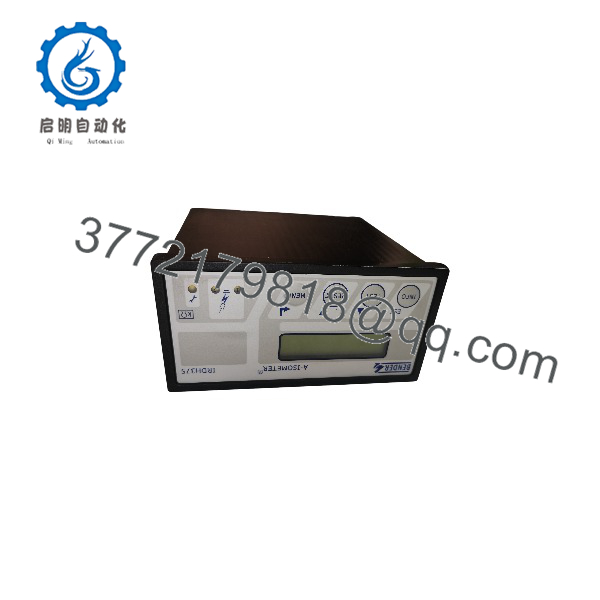
IRDH375B-435
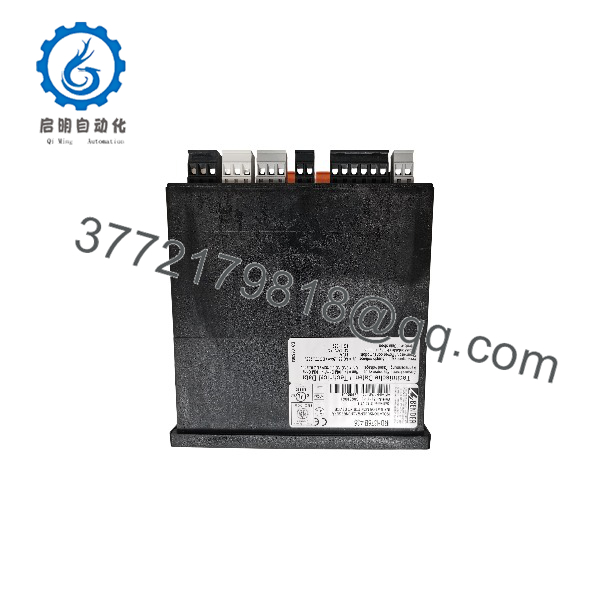
IRDH375B-435
Troubleshooting Quick Reference
| Symptom | Possible Cause | Relevance to This Part | Quick Check Method | Recommendation |
|---|---|---|---|---|
| No display or status LEDs | Missing supply, incorrect supply variant, blown upstream fuse, internal fault | ✅ High | Measure 88–264 V AC or 77–286 V DC at A1/+ and A2/−; verify the supply fuse | Confirm the supply range and wiring before replacing the monitor |
| Low insulation alarm appears | Real insulation fault, moisture, damaged cable, motor fault, filter leakage | ✅ High | Isolate feeders one at a time and test the de-energized branch with an approved insulation tester | Locate the field fault; replacing the IRDH375B-435 will not correct a real ground fault |
| Alarm occurs when a VFD starts | Drive filter leakage, motor-cable capacitance, inverter fault, alarm threshold too high | ⚠️ Medium | Compare the insulation value with the VFD isolated and energized; review CeC_e | Check the drive, motor, cable, and leakage-capacitance limit before replacing the device |
| Display shows “Connection PE?” | Missing or high-resistance protective-earth connection at ⏚/KE | ✅ High | Verify continuity from ⏚ and KE to the protective conductor; inspect the terminal wiring | Repair the PE/KE connection, then run the TEST function |
| Display shows “System connection?” | L1/L2 not connected to the monitored IT system, open fuse, or wiring error | ✅ High | Check continuity and voltage at L1/L2 according to the approved wiring diagram | Correct the measurement connections before condemning the monitor |
| Alarm relays do not operate | Wrong relay operating mode, alarm threshold not crossed, failed relay, wiring error | ✅ High | Run the manual TEST function and measure K1/K2 contacts with a multimeter | Verify relay mode and external wiring; replace only after the relay test fails |
| Alarm remains after repair | Fault memory enabled, reset input open, insulation value not above reset hysteresis | ✅ High | Check memory setting and RESET wiring at R1/R2; verify the measured value exceeds the reset level | Clear the fault only after confirming the system is safe and insulation has recovered |
| Analog output is missing | Wrong 0–20 mA / 4–20 mA mode, open loop, excessive burden, wiring error | ⚠️ Medium | Measure current at M+/M− and verify the receiving impedance is no more than 500 Ω | Correct the loop wiring and scaling; do not apply external voltage to the output |
| BMS network cannot see the device | Wrong address, reversed A/B conductors, missing termination, incompatible protocol | ✅ High | Confirm BMS address, polarity, cable shield, and 120 Ω termination at the correct bus end | Configure the host for Bender BMS; this is not the one-way ASCII interface used by IRDH375 |
| Multiple insulation monitors interfere | More than one active ISOMETER on an interconnected IT system | ✅ High | Identify every monitor connected through the coupled system and check F1/F2 or ISOnet settings | Keep only one monitor active or configure the BMS/standby arrangement correctly |
| Device enters STANDBY | F1/F2 function input closed or external coupling-control signal active | ✅ High | Measure continuity across F1/F2 and inspect the interlock or breaker auxiliary contact | Open the standby command only when the system architecture permits monitoring |
| Event history has wrong times | Real-time clock not configured or backup interval exceeded | ❌ Low | Open the HISTORY menu and compare the clock/date with a reference time | Set the clock during commissioning and document the time zone |
| Self-test reports internal device error | Internal electronics, measurement circuit, or memory fault | ✅ High | Press TEST, record the exact error message, and cycle power only under an approved procedure | Escalate to Bender service or replace with a verified compatible unit |
Support note: Contact technical support with the full nameplate, material number, LCD message, BMS address, alarm settings, system voltage, measured leakage capacitance, wiring photos, and event history.
Frequently Asked Questions (FAQ)
What does the Bender IRDH375B-435 monitor?
It continuously monitors insulation resistance between an unearthed IT system and protective earth. It is suitable for AC, DC, and mixed AC/DC systems up to 793 V AC or 650 V DC.
What does the “B” version add?
The IRDH375B version adds a real-time clock and history memory, an electrically isolated RS-485 interface with Bender BMS protocol, an isolated 0/4–20 mA output, and standby/disconnection functions for interconnected IT systems.
What is the difference between and IRDH375-435?
Both versions monitor the same nominal system-voltage range and use the same high-voltage auxiliary supply. The IRDH375-435 uses a 0–400 μA output and one-way ASCII communication, while the uses an isolated 0/4–20 mA output and two-way BMS communication. They are not communication-equivalent replacements.
Is the DIN-rail mounted?
No. The is a panel-mounted instrument with a front display and rear screw terminals. The Bender IRDH275 family is the DIN-rail-style alternative, but it is not automatically a functional or mechanical replacement for an .
Can it monitor systems with variable-frequency drives?
Yes. The AMPPlus measurement method is intended for modern IT systems containing rectifiers, converters, and variable-frequency drives. However, drive filters and long motor cables can increase leakage capacitance and produce genuine or application-related alarms. Investigate the power system before changing the monitor.
Can I perform an insulation test while the remains connected?
No. Bender’s manual states that the ISOMETER must be disconnected from the IT system during insulation or voltage tests. Applying a megohmmeter or hipot test through the connected monitor can damage the device.
Is the still available as a new factory part?
Availability depends on current production and distributor inventory. The model is an older IRDH375 family device, so listings may include new surplus, used, or refurbished units. Request the exact material number B91065004, nameplate photo, condition, software version, test report, warranty, and return terms before purchasing.



