
 WhatsApp: +86 16626708626
 Email:
  Phone: +86 16626708626
Description
Key Technical Specifications
| Parameter | Value |
|---|---|
| Model | IRDH575B1W-435 |
| BENDER Article No. | B91065500W |
| Product Family | ISOMETER IRDH575 |
| Device Type | Insulation monitoring device |
| Nominal System Voltage | AC 20–575 V; 3/(N)AC; DC 20–575 V |
| Nominal Frequency | 50–460 Hz |
| Auxiliary Supply | AC 88–264 V / DC 77–286 V |
| Supply Frequency | 42–460 Hz |
| Insulation Response Range | 1 kΩ–10 MΩ |
| Alarm Thresholds | Alarm 1 and Alarm 2, independently adjustable |
| Measuring Voltage | ≤40 V |
| Measuring Current | ≤220 μA at Rf = 0 Ω |
| System Leakage Capacitance | Up to 500 μF |
| Analog Output | 0/4–20 mA, maximum load 500 Ω |
| Serial Interface | RS-485 |
| Protocol | BMS |
| RS-485 Maximum Cable Length | ≤1,200 m |
| Terminating Resistor | 120 Ω, 0.5 W |
| Relay Outputs | 3 changeover contacts: K1, K2, K3 |
| Display | Illuminated 4-line LCD, 4 × 16 characters |
| Operating Temperature | −25 to +70 °C with W option |
| Storage Temperature | −40 to +85 °C with W option |
| Shock Resistance | 30 g / 11 ms during operation |
| Vibration Resistance | 1.6 mm / 10–25 Hz; 4 g / 25–150 Hz |
| Protection Rating | IP30 internal; IP20 terminals; up to IP65 with specified transparent cover |
| Mounting | Panel mounting / display-oriented installation |
| Weight | ≤900 g |
BENDER specifies the IRDH575B1-435 for AC/DC systems from 20 to 575 V, with AC 88–264 V or DC 77–286 V auxiliary supply. The device provides RS-485/BMS communication, three changeover contacts, and a 0/4–20 mA output.
The W option is not merely a cosmetic suffix. BENDER documents enhanced shock and vibration resistance plus a special coating intended to improve resistance to mechanical stress and moisture. The W version is intended for applications such as marine, rail, and seismic environments.
Product Introduction
The BENDER IRDH575B1W-435 is an ISOMETER insulation monitoring device for unearthed AC and DC IT systems with nominal voltages from 20 to 575 V. It monitors insulation resistance from 1 kΩ to 10 MΩ and provides two configurable alarm thresholds, three relay outputs, RS-485/BMS communication, and a 0/4–20 mA analog output.
The W version adds increased resistance to shock, vibration, and moisture compared with the standard IRDH575B1-435. That distinction matters in rolling stock, marine equipment, and installations exposed to mechanical vibration or seismic conditions.
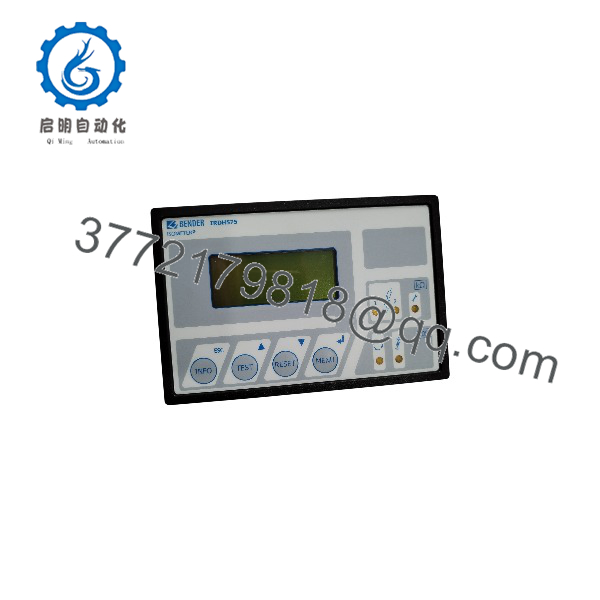
IRDH575B1W-435
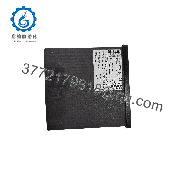
IRDH575B1W-435
Installation & Configuration Guide
Stage 1: Pre-Installation Preparation — Approximately 5–10 Minutes
⚠️ Safety First: The IRDH575 is connected to the monitored electrical system and has an auxiliary supply as high as 264 V AC. Qualified electrical personnel should perform the replacement. Notify operations, establish a safe operating state, apply lockout/tagout, and verify the absence of hazardous voltage before disconnecting the device.
- Isolate the monitored circuit and auxiliary supply according to the plant electrical isolation procedure.
- Wait at least 5 minutes for associated equipment to discharge, while following the site’s electrical safety requirements.
- Prepare:
- ESD wrist strap
- PH1 screwdriver
- Properly rated multimeter
- Wire labels
- Smartphone or camera
- Appropriate terminal tools
- Photograph the complete terminal arrangement before removing anything.
- Record the existing:
- Alarm 1 setting
- Alarm 2 setting
- BMS address
- BMS wiring polarity
- Relay contact assignments
- Analog output configuration
- Test/reset arrangement
- Any EDS/insulation-fault-location configuration
- Verify the replacement is specifically IRDH575B1W-435, not IRDH575B1-435, IRDH575B2-435, or another IRDH575 variant.
⚠️ Do not use the 24 V replacement procedure blindly here. The -435 version uses AC 88–264 V or DC 77–286 V auxiliary power.
Stage 2: Removing the Old Module — Approximately 5 Minutes
- Verify isolation with an appropriately rated multimeter.
- Remove the front/access components necessary to reach the terminals.
- Label every conductor individually.
- Photograph the terminal wiring again immediately before disconnecting it.
- Disconnect the conductors without pulling or twisting the terminals.
- Release the panel mounting mechanism.
- Remove the IRDH575 carefully and inspect the surrounding wiring and enclosure.
- Check for loose strands, damaged insulation, corrosion, or evidence of overheating.
- Keep the original device available for configuration comparison until commissioning is complete.
⚠️ Do not assume another IRDH575 variant is a direct electrical substitute. BENDER specifies different system-voltage ranges and supply configurations for B1, B2, and -427/-435 variants.
Stage 3: Installing the New Module — Approximately 5–10 Minutes
- Verify the nameplate: IRDH575B1W-435.
- Confirm the ordering reference against the required configuration: B91065500W.
- Inspect the enclosure, display, terminals, and mounting hardware for shipping damage.
- Wear an ESD wrist strap when handling the electronic assembly.
- Install the unit securely in the panel.
- Reconnect all conductors according to the original wiring record and the BENDER connection diagram.
- Preserve the correct RS-485/BMS polarity and bus topology.
- Check the RS-485 termination. BENDER specifies a 120 Ω / 0.5 W terminating resistor and maximum cable length of 1,200 m.
- Reconnect the relay outputs according to their original function:
- K1: Alarm 1
- K2: Alarm 2
- K3: Device error / selectable EDS alarm
- Reconnect the analog output and verify whether the plant expects 0–20 mA or 4–20 mA.
- Tighten terminals according to the applicable BENDER installation specification.
Configuration Clone — Critical
Copy the old device’s:
- Alarm 1 threshold
- Alarm 2 threshold
- BMS address
- Relay operating mode
- Analog-output setting
- Test/reset configuration
- EDS parameters, if used
- Date/time and other application-specific parameters
Self-Checklist
- Exact IRDH575B1W-435 model verified
- B91065500W reference verified
- AC/DC auxiliary supply verified
- Monitored voltage within 20–575 V range
- BMS A/B wiring verified
- 120 Ω termination checked
- Alarm thresholds copied
- Relay functions copied
- Analog output configuration copied
- Terminals secured
- Panel mounting secure
Stage 4: Power-On & Testing — Approximately 10–15 Minutes
- Perform a final wiring inspection before energizing.
- Verify the auxiliary supply against the -435 specification.
- Energize the device according to the approved commissioning procedure.
- Confirm the illuminated four-line display starts normally.
- Allow the device’s self-test to complete.
- Verify the displayed insulation resistance is plausible for the monitored system.
- Enter the configuration menu and verify Alarm 1 and Alarm 2.
- Confirm the BMS address and establish RS-485/BMS communication with the plant monitoring system.
- Verify the 0/4–20 mA output at the receiving PLC/DCS or measuring instrument.
- Check K1, K2, and K3 relay behavior using the approved test procedure.
- If the installation uses insulation-fault location, verify the EDS configuration and locating-current settings.
- Record the final settings and commissioning results.
The IRDH575 family provides adjustable insulation response values from 1 kΩ to 10 MΩ, with two alarm thresholds and a separate device-error relay. Its EDS function can use locating currents of 1, 2.5, 10, 25, or 50 mA.
⚠️ Do not create an uncontrolled insulation fault on a live production circuit merely to test the alarm. Use the manufacturer’s test function or an approved controlled test method.
Frequently Asked Questions (FAQ)
1. What is the BENDER IRDH575B1W-435 used for?
It monitors insulation resistance in unearthed AC and DC IT systems with nominal system voltages from 20 to 575 V. It can also work with insulation-fault-location equipment as part of a BENDER monitoring system.
2. What does the “W” suffix mean?
The W option adds enhanced mechanical and environmental resistance. BENDER specifies higher shock and vibration resistance and a special coating intended to increase resistance to mechanical stress and moisture. This option is associated with applications such as marine, railway, and seismic environments.
3. What is the BENDER part number for ?
The standard IRDH575B1-435 is listed as B91065500. With the W option, the corresponding ordering reference is B91065500W. Verify the actual nameplate before purchasing because B1 and B2 variants have different monitored-voltage ranges.
4. Can I replace an IRDH575B1-435 with an ?
From the electrical configuration standpoint, both are B1-435 variants with the same 20–575 V monitored-system range and 88–264 V AC / 77–286 V DC auxiliary supply. The W version adds environmental and mechanical resistance. However, verify the complete ordering code and physical installation requirements before substitution, particularly where certification, enclosure conditions, or environmental specifications are part of the equipment approval.
5. Does the communicate with a BENDER BMS system?
Yes. The uses RS-485 with the BENDER BMS protocol. BENDER specifies a maximum RS-485 cable length of 1,200 m and a 120 Ω terminating resistor. Wiring polarity and termination must be checked during replacement.
6. Can this unit be hot-swapped?
Do not treat it as a hot-swappable I/O module. The connects directly to the monitored electrical system and its auxiliary supply. De-energize and isolate the relevant circuits according to the plant’s electrical safety procedure before removing the device.
7. Is the new, surplus, or refurbished?
The model number does not establish physical stock condition. A procurement team should request the actual nameplate photograph, serial number, packaging condition, and test documentation for the offered unit.
For a New Original/New Surplus unit, confirm that the seller identifies the condition explicitly. For a refurbished unit, request the functional test report and test date. Do not treat “unused” and “factory sealed” as equivalent descriptions.



