
 WhatsApp: +86 16626708626
 Email:
  Phone: +86 16626708626
Description
Key Technical Specifications
- Part Number: 140734-02
- Associated Model: 3500/42M
- Brand: Bently Nevada
- Product Type: 3500/42M Proximitor Seismic Monitor
- Channels: 4
- Input Signal: 1 to 4 proximity, velocity, or acceleration transducer signals
- Standard I/O Impedance: 10 kΩ (Proximitor and acceleration inputs)
- Power Consumption: 7.7 W typical
- Transducer Power Supply: -24 Vdc
- Buffered Transducer Outputs: 1 coaxial connector per channel (front-mounted), short-circuit protected
- Output Impedance: 550 Ω
- Recorder Output: +4 to +20 mA
- Voltage Compliance: 0 to +12 Vdc across load
- Shaft Absolute Output Impedance: 300 Ω
- Accuracy: ±0.33% full-scale typical, ±1% maximum
- Direct Filter: -3 dB at 1.2 Hz
- Gap Filter: -3 dB at 0.41 Hz
- Resolution: 0.3662 µA per bit ±0.25% (room temp)
- LED Indicators: OK LED (operating status), TX/RX LED (rack communication), Bypass LED (bypass mode)
- Dimensions: 263 × 58 × 28 mm (10.35 × 2.28 × 1.1 in) or 16 cm × 16 cm × 12 cm
- Weight: 0.8–0.85 kg
- Country of Origin: United States (Minden, Nevada)
- Monitoring Capabilities: Radial vibration, thrust position, differential expansion, eccentricity, REBAM, acceleration, velocity, shaft absolute circular acceptance region
Product Introduction
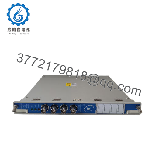
Bently Nevada 140734-02 is the 3500/42M Proximitor Seismic Monitor, a four-channel monitor for the 3500 Machinery Protection System. It accepts input from proximity, velocity, and acceleration transducers, conditions the signal for vibration and position measurements, and compares results against user-programmable alarm setpoints.
This module is chosen when the site needs versatile 4-channel monitoring for radial vibration, thrust position, differential expansion, eccentricity, REBAM, acceleration, or velocity on turbines, compressors, and large rotating equipment. The buffered transducer outputs provide short-circuit protected coaxial signals per channel for external monitoring or recording.

- 140734-02
- 140734-02

Troubleshooting Quick Reference
| Symptom | Possible Cause | Relevance to this Part | Quick Check Method | Recommendation |
|---|---|---|---|---|
| No LEDs on module (black screen) | Rack power loss or backplane issue | ❌ Low | Measure rack supply at backplane; check adjacent modules for power | Check the 3500 rack PSU and slot power before replacing the module |
| OK LED off or flashing | Module fault or configuration mismatch | ✅ High | Read diagnostic buffer in 3500 software; verify module type matches rack config | Reload correct configuration and confirm module ID in 3500 system |
| TX/RX LED not lit | Rack communication failure | ✅ Medium | Check rack communication wiring and compare module type against configuration | Verify 3500 rack communication setup and reload config if needed |
| Bypass LED on | Module in bypass mode (manual or fault) | ✅ Medium | Check 3500 software for bypass status and review alarm history | Exit bypass mode via software after confirming no active faults |
| One channel unresponsive, others normal | Local channel failure or external transducer fault | ✅ High | Swap the transducer to a known-good channel and compare readings | Replace transducer or wiring first; replace module only if channel still dead |
| Buffered output shows no signal | Transducer not powered or probe gap wrong | ✅ High | Measure -24 Vdc transducer supply at the probe; check probe gap and signal amplitude | Re-set probe gap or replace transducer before declaring module faulty |
| Alarm triggered unexpectedly | Probe gap drift, wiring noise, or setpoint wrong | ✅ High | Review alarm history and verify probe gap, wiring, and setpoint values | Adjust setpoint or fix wiring/probe gap before replacing module |
| Vibration/position reading unstable | Loose wiring, damaged sensor, or poor shielding | ✅ Medium | Inspect terminations and measure signal at module input with oscilloscope | Repair wiring or swap the transducer; check shield grounding |
Contact technical support with photos of the front label, rack slot, wiring diagram, probe gap measurements, buffered output readings, and diagnostic buffer logs if the fault is still unclear.
Frequently Asked Questions
Can I use 140734-02 as a direct replacement for an older 4-channel monitor?
Yes, if your rack and configuration match the existing 3500/42M setup. Verify the exact slot type, I/O termination style, alarm configuration, and buffered output routing before swapping it in.
Is this module hot-swappable?
Do not assume hot-swap is supported. Pulling a monitor without confirming the 3500 rack procedure can create a fault or disturb monitor modules, so power down or follow the site maintenance method first.
Will my existing configuration transfer automatically?
No, not always. The replacement may need the same rack setup, channel mapping, alarm thresholds, and buffered output configuration loaded again. Take screenshots or backup files before removal.
What transducer types does this monitor accept?
It accepts 1 to 4 proximity, velocity, or acceleration transducer signals. This makes it suitable for radial vibration, thrust position, differential expansion, eccentricity, REBAM, and shaft absolute monitoring.
Why is surplus stock cheaper than factory new?
Surplus parts often come from excess inventory, decommissioned systems, or channel stock. The price is lower, but you still need a clear test record and condition statement (New Original, New Surplus, or Refurbished tested).
What condition should I expect on a surplus unit?
For a credible sale listing, state whether it is New Original, New Surplus, or Refurbished (tested). Buyers in this market want the truth up front, not a vague “used” label.
Does this part fail often?
Not usually. In practice, the probe, velocity transducer, accelerometer, wiring, probe gap, or rack power/configuration causes more trouble than the monitor itself. Verify the system around it before replacing the module. The buffered outputs and -24 Vdc transducer supply are common check points.


