
 WhatsApp: +86 16626708626
 Email:
  Phone: +86 16626708626
Description
3. Key Technical Specifications
| Parameter | Value |
|---|---|
| Product Type | FieldMonitor™ Isolator Terminal Base |
| Model | 1701/06 |
| Input Power | +19 VDC to +33 VDC |
| Typical System Power Dissipation | 36 W @ 24 VDC |
| Module Capacity | Up to 4 two-channel monitor modules |
| Mounting | Bulkhead or 35 mm DIN rail |
| Dimensions | 127 × 203.2 × 508 mm (5 × 8 × 20 in.) |
| Weight | 1.6 kg (without modules) |
| Operating Temperature | -20 °C to +70 °C |
| Storage Temperature | -40 °C to +85 °C |
| Humidity | 5–95% RH, non-condensing |
| Hazardous Area Certifications | CSA Class I Div 2, ATEX Zone 2 (configuration dependent) |
The 1701/06 serves as the FieldMonitor platform for installing monitor modules, galvanic isolators, transducer I/O modules, power supply, and communication interface in a single assembly. It supports intrinsically safe transducer installations when paired with the appropriate 170190 Dual Galvanic Isolators.
4. Product Introduction
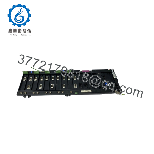
The Bently Nevada 1701/06 FieldMonitor Isolator Terminal Base is the mechanical and electrical foundation of the FieldMonitor machinery protection platform. It houses monitor modules, transducer interfaces, galvanic isolators, the power supply, and communication hardware for continuous vibration and condition monitoring.
In existing installations, the 1701/06 remains a practical choice because it allows hazardous-area transducer connections without external Zener barriers when used with compatible 170190 isolators. Before installation, verify module compatibility, firmware revisions, and hazardous-area approvals for the specific application.

- 1701/06
5. Installation & Configuration Guide
Stage 1 – Pre-Installation Preparation (10 minutes)
⚠️ Safety First
- Notify operations of the planned shutdown.
- Lock out and tag out all power sources.
- Wait at least 5 minutes for internal capacitors to discharge.
- Verify zero voltage using a calibrated multimeter.
Tools Required
- Grounded ESD wrist strap
- PH1 screwdriver
- Fluke 115 (or equivalent) multimeter
- Wire labels
- Smartphone for documentation
Data Backup
- Export the FieldMonitor configuration.
- Record network settings.
- Photograph every terminal connection.
- Photograph all DIP switches and jumper settings.
- Record installed module locations.
Stage 2 – Removing the Old Module (5–10 minutes)
- Remove the front cover.
- Label every field cable before disconnecting.
- Remove monitor and interface modules if necessary.
- Release mounting hardware.
- Pull the terminal base straight out without twisting.
Inspect:
- Backplane connectors
- Bent pins
- Dust accumulation
- Corrosion
⚠️ Keep the old assembly until commissioning is complete.
Stage 3 – Installing the New Module (10 minutes)
- Wear an ESD wrist strap.
- Verify 1701/06 matches the replacement.
- Install the terminal base securely.
- Reinstall all modules in their original slots.
- Reconnect wiring according to photographs.
- Tighten terminal screws to the specified torque.
Configuration Clone (Critical)
Replicate every:
- DIP switch
- Jumper
- Node address
- Bus termination setting
Self Checklist
- ☑ Model verified
- ☑ Wiring complete
- ☑ DIP switches duplicated
- ☑ Mounting secure
- ☑ Earth connections installed
Stage 4 – Power-On & Testing (10–15 minutes)
Before Applying Power
- Check 24 V rail for shorts.
- Verify protective earth continuity.
Power-Up Sequence
- Energize the rack.
- Observe LED startup sequence.
- Verify communication with the management interface.
- Confirm firmware versions.
- Restore configuration if required.
- Simulate transducer inputs.
- Verify alarm functions.
- Confirm all communication channels.
⚠️ Troubleshooting
- Solid ERR LED: Firmware revision mismatch is the first item to investigate.
- No communications: Check network settings, Flexbus connections, and Management Interface configuration.
- Missing transducer signal: Verify the correct 170190 galvanic isolator and compatible transducer I/O module are installed.
Common Replacement Pitfalls
❗ Firmware Revision Mismatch
I’ve seen maintenance teams replace only the hardware while overlooking firmware compatibility. The hardware powered up normally, but communication faults continued until the original firmware revision was restored. Always document firmware before removing the old assembly.
❗ DIP Switch Configuration
This is probably the most common mistake. Take a clear photo before removing the old unit. Copy every switch exactly.
❗ Terminal Wiring Differences
Never wire from memory. Even similar assemblies may have different terminal assignments depending on the installed transducer modules.
❗ Power Budget
A fully populated FieldMonitor rack draws considerably more current than an empty chassis. Verify the 24 VDC supply has at least 20% reserve capacity before adding additional monitor modules.
❗ ESD Protection
I have watched perfectly good electronics fail because someone skipped the wrist strap during a winter shutdown. Handle every module on an ESD-safe surface.
Keep these checks in mind and you’ll avoid most commissioning delays.
6. Frequently Asked Questions (FAQ)
Q1. Can I hot-swap the 1701/06?
No. The terminal base is not designed for live replacement. Remove system power before installation to avoid damaging the backplane or connected modules.
Q2. Is the 1701/06 obsolete?
Yes. The FieldMonitor platform has been discontinued for many years. Genuine new surplus inventory is still available through independent industrial automation suppliers, but availability is becoming limited.
Q3. Does the 1701/06 include monitor modules?
No. The 1701/06 is only the Isolator Terminal Base. Monitor modules, the 1701/10 power supply, 1701/22 management interface, transducer I/O modules, and 170190 galvanic isolators are ordered separately.
Q4. Will replacing the terminal base erase my machine configuration?
No. Configuration is normally stored within the monitoring electronics rather than the passive terminal base. Even so, always back up the system configuration before maintenance.
Q5. What is the direct replacement if the 1701/06 is unavailable?
There is no drop-in replacement. Existing installations generally continue using surplus OEM inventory or migrate to newer Bently Nevada condition monitoring platforms, which usually requires engineering changes rather than a simple hardware swap.
Q6. Why is New Surplus inventory less expensive than buying from the OEM?
Most New Surplus inventory comes from unused project stock, plant closures, or excess distributor inventory. The hardware has never been placed into service but may no longer be in current OEM production. Verify packaging, serial numbers, and functional test reports before purchase.
Q7. What quality inspections should be completed before shipment?
A proper inspection process should include:
- OEM serial number verification
- Anti-counterfeit inspection
- Visual inspection for corrosion, scratches, or repair marks
- Functional testing on a genuine FieldMonitor test rack
- Communication verification
- Insulation resistance testing (>10 MΩ at 500 V Megger where applicable)
- Firmware documentation
- QC sign-off
- ESD packaging
- Heavy-duty export packaging
Test photos and functional test videos should be available upon request.



