
 WhatsApp: +86 16626708626
 Email:
  Phone: +86 16626708626
Description
3. Key Technical Specifications
| Parameter | Specification Value |
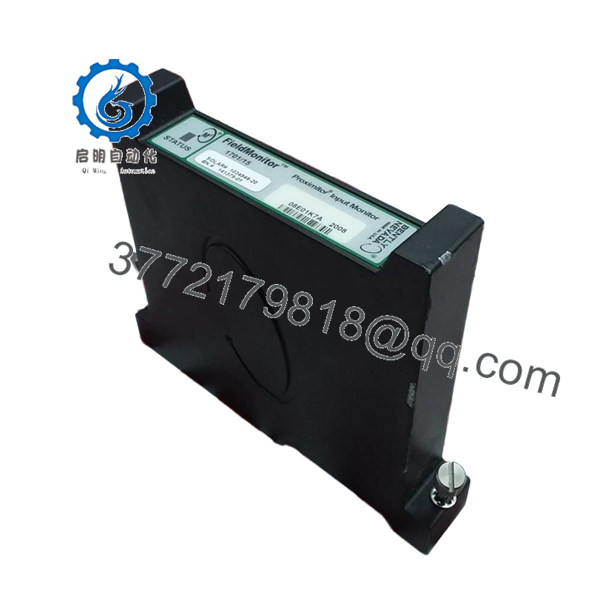
| Module Type | Trendmaster Pro Keyphasor / Phase Reference Module |
| Input Signals | Accepts pulses from eddy current proximity transducer probes |
| Channel Density | Multi-channel architecture for independent phase tracking |
| Transducer Supply | −24 VDC internally generated sensor power |
| Frequency Range | 1 to 100,000 cpm (0.017 Hz to 1.67 kHz) |
| Pulse Width Minimum | 10 microseconds |
| Buffered Outputs | Front-panel coaxial or terminal breakout interfaces |
| Network Interface | Internal high-speed backbone connection within 1701 chassis |
| Operating Temperature | −30 to +65 °C (−22 to +149 °F) |
| Hazardous Approvals | CSA Class I Div 2, ATEX Zone 2 compliant |
4. Product Introduction & Supply Chain Strategy
The Bently Nevada 1701/15 is a high-speed Keyphasor module designed for the Trendmaster Pro platform. It provides the timing foundation required for predictive vibration diagnostics across complex industrial rotating assets, including turbines, compressors, and high-horsepower electric motors. The module processes raw voltage pulses from proximity probes, turning them into once-per-turn phase references. These reference signals allow plant instrumentation systems to measure exact rotational speed and correlate vibration waveforms with specific angular positions on the machine shaft.
As plants shift maintenance budgets toward targeted online monitoring, relying on aging or second-hand telemetry cards like the 1701/15 poses a significant risk to operations. Refurbished dynamic signal processors frequently suffer from degraded tracking circuitry, leading to false phase readings or missed velocity spikes that blind engineers to catastrophic shaft misalignments. Choosing a factory-sealed, New Surplus asset ensures the tight tolerances required for dynamic signal conditioning remain intact. This technical sourcing strategy guarantees accurate predictive asset analytics, provides immediate protection against long lead-time stock-outs, and reduces overall lifecycle costs compared to expensive system retrofits.

- 1701/15
5. Installation & Configuration Guide
Stage 1: Pre-Installation (Prep & Safety)
- Verify that the primary 1701 system rack power supply is completely switched off and locked out.
- Ensure that any machinery diagnostic software polling the target Trendmaster hub is placed into a temporary service bypass mode.
- Put on a certified ESD grounding wrist strap, ensuring the reference lead is securely clamped to the bare metal chassis frame.
- Document the existing field wiring layout on the backplane or terminal block, noting signal wire colors and probe shielding points.
Stage 2: Removal
- If applicable, disconnect any coaxial test leads from the buffered front-panel diagnostic jacks.
- Loosen the upper and lower faceplate screws that secure the card to the subrack mounting frame.
- Grasp the module ejector handles or faceplate firmly, drawing it outward in a straight line to disengage the backplane gold edge-connectors.
- Slide the module completely clear of the internal chassis guide slots, and place the card directly into an ESD shielding pouch.
Stage 3: Installation (Clone & Seat)
- Withdraw the replacement New Surplus 1701/15 card from its sealed anti-static bag.
- Check the physical orientation of any onboard hardware DIP switches or jumpers against the original module, matching configuration profiles exactly.
- Line up the card edges with the plastic card guides inside the vacant slot of the 1701 housing.
- Press the card into the slot with a firm, steady motion until the faceplate flange rests flush against the rack frame, then secure the retaining screws.
Stage 4: Power-On & Testing
- Re-energize the main power source feeding the 1701 telemetry chassis.
- Observe the front panel LED diagnostic indicators: the green power or health lamp should steady within seconds.
- Verify that the Keyphasor pulse trigger indicator blinks in direct synchronization with the physical rotation of the monitored machine shaft.
- Open the System 1 software workstation to confirm that the phase telemetry stream is online, showing valid, uncorrupted RPM and angle data.
6. Firmware/Software Versions & Upgrade Notes
The 1701/15 relies on digital logic firmware to properly process high-frequency input streams across the Trendmaster interface. When introducing a New Surplus card to an existing installation, you must check the module’s core revision letter against the master firmware profile of the 1701 network controller block.
Connecting modules with conflicting firmware versions can cause communication timeouts or prevent the main diagnostic software from parsing dynamic pulse data. If your site’s monitoring software demands a specific firmware baseline, you must flash or synchronize the new module using an authorized configuration utility before launching critical asset tracking runs. Always back up existing software settings and verify network link stability before running a firmware modification to avoid bricking the onboard processor.
7. Frequently Asked Questions (FAQ)
Q: Why should we buy a New Surplus 1701/15 card rather than a repaired or refurbished unit?
A: Keyphasor circuits require high timing accuracy to properly diagnose machine health. Refurbished modules often carry hidden component degradation from long runtime exposures inside hot field enclosures, which can cause phase readings to drift over time. This New Surplus module provides unpowered, factory-fresh processing paths, giving you OEM-grade reliability without long production backorders.
Q: Does this Keyphasor card arrive inside original factory boxes?
A: Yes. All our New Surplus inventory is shipped in original factory packaging or high-grade ESD-safe equivalent boxes. Our internal quality teams open these containers solely to perform controlled visual tracking and electrical validation checks prior to dispatch.
Q: Can this 1701 series card be pulled or replaced while the rack is live?
A: No. The 1701 monitoring architecture requires a clean power isolation sequence before card extraction. Pulling a Keyphasor card while the internal backplane bus is energized can create an inductive arc that damages the board’s sensitive edge connectors or disrupts data traffic across adjacent vibration monitoring cards.
Q: What happens if the internal jumper for transducer voltage is set incorrectly?
A: The module must be matched to the power requirements of your specific proximity probe (typically −24 VDC). If the onboard jumpers do not match your field sensors, the probe will not receive proper power, resulting in a zero-voltage fault or a complete loss of speed telemetry in your diagnostic software.
Q: Does this module include the proximity sensor probe itself?
A: No. The 1701/15 is the rack-mounted electronic processing card. The physical proximity probes, extension cables, and sensor housings located on the machine frame are separate components that must be ordered and specified based on your physical shaft layout.
Q: What type of warranty protection covers this New Surplus asset?
A: We provide a comprehensive 1-to-2 year replacement warranty on this module. This commitment matches or exceeds typical OEM new-equipment policies, offering complete financial and operational security for your plant maintenance budgets.


