
 WhatsApp: +86 16626708626
 Email:
  Phone: +86 16626708626
Description
3. Key Technical Specifications
| Parameter | Specification Value |
| Part Number | 176449-01 (Standard 3500/40M Monitor Module) |
| Number of Channels | 4 channels per module (accepts up to 4 proximity probes) |
| Input Signals | Non-contacting proximity transducer systems (7 mm, 8 mm, 11 mm Proximitor) |
| Power Consumption | 7.7 W nominal maximum draw |
| Signal Processing | Radial vibration, axial thrust position, eccentricity, differential expansion |
| Recorder Outputs | True 4 to 20 mA DC outputs per channel (proportional to value) |
| Accuracy | Within ±1% of full-scale range |
| Buffered Transducer Outputs | Front panel coaxial BNC connectors (100 \Omega output impedance) |
| Isolation Barrier | 500 V RMS galvanic isolation from field wiring to rack logic |
| Operating Temperature | −30 to +65 °C (−22 to +149 °F) |
4. Product Introduction & Supply Chain Strategy
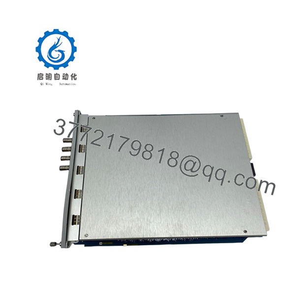
The Bently Nevada 3500/40M 176449-01 is a four-channel Proximitor monitor module designed for the 3500 Series Machinery Protection System. The module receives analog voltage waveforms from field-mounted eddy current proximity probes, processing the inputs in real time to measure radial shaft vibration, axial thrust position, eccentricity, and thermal expansion. It serves as a primary safety boundary for critical high-speed rotating assets—such as steam turbines, centrifugal compressors, and large generator sets—by comparing vibration levels against predefined alarm limits and sending trip signals to emergency shutdown systems before mechanical failure occurs.
Sourcing the 176449-01 as a New Surplus asset provides a vital safety net for critical machinery protection programs. Refurbished dynamic vibration modules are highly susceptible to component aging, leading to channel drift, calibration errors, or missed high-frequency spikes that can leave a spinning turbine unprotected. Choosing factory-sealed, unpowered surplus inventory ensures the tight accuracy tolerances required for machinery protection are fully intact. This technical sourcing approach significantly reduces your Total Cost of Ownership (TCO) by avoiding long factory production lead times and providing a zero-hour, drop-in replacement for unexpected forced outages.
5. Installation & Configuration Guide
Stage 1: Pre-Installation (Prep & Safety)
- Verify that the machinery protection rack is placed in bypass or that the protective trip relays associated with the slot are safely disarmed.
- Ensure the primary rack power supply remains stable and that your engineering workstation is connected to the 3500 rack via the 3500 Rack Configuration Software.
- Wear a calibrated, grounded ESD wrist strap connected directly to an unpainted, metallic surface on the 3500 rack chassis frame.
- Upload and back up the current rack configuration profile (
.w35format) to your workstation before removing any hardware.
Stage 2: Removal
- Unplug any coaxial patch cables connected to the front-panel BNC buffered transducer outputs.
- Loosen the upper and lower captive thumbscrews on the 3500/40M monitor module faceplate using a flathead screwdriver.
- Open the ejector handles outward simultaneously to unseat the module’s high-density rear connectors from the rack backplane.
- Pull the module straight out of the chassis guides with a smooth, even motion, and slide it immediately into an anti-static shielding bag.
Stage 3: Installation (Clone & Seat)
- Remove the New Surplus 3500/40M 176449-01 module from its sealed anti-static packaging.
- Inspect the rear backplane connector pins to confirm they are straight, clean, and free of debris.
- Align the module circuit board with the plastic card guides inside the designated dual-slot location.
- Slide the card backward into the slot until the ejector handles touch the chassis frame, then press the handles inward to seat the module connectors into the backplane. Tighten the captive faceplate screws.
Stage 4: Power-On & Testing
- Observe the front panel LED startup sequence: the OK LED should blink during initialization and then turn a solid green.
- Verify that the bypass indicator light clears once the module completes its power-on self-test (POST).
- Connect an oscilloscope to the front-panel BNC buffered outputs to confirm the gap voltage and raw AC vibration waveforms match your field baseline measurements.
- Use the 3500 Configuration Software to download the original channel configuration to the new module, then clear any temporary latching alarms.

- 3500/40M 176449-01
6. Firmware/Software Versions & Upgrade Notes
The 3500/40M 176449-01 module relies on internal digital signal processor (DSP) firmware to filter and calculate machine telemetry. This firmware must remain fully compatible with both the 3500/22M Transient Data Interface (TDI) module and the specific version of the 3500 Rack Configuration Software running on your plant network.
When installing a New Surplus module, connecting it to a system with mismatched firmware can cause the TDI to flag an unconfigured module or block data synchronization across the internal backplane bus. If the new module arrives with a firmware revision that does not match your factory baseline, you must flash the module using the configuration utility to align it with your plant standard. Ensure that rack communication links are secure and power remains uninterrupted during the flash process to prevent damaging the board’s bootloader.
7. Frequently Asked Questions (FAQ)
Q: Why choose a New Surplus 3500/40M module over a repaired or refurbished unit?
A: Machinery protection monitors handle critical safety loops where a missed vibration spike can lead to catastrophic turbine failure. Refurbished modules are often exposed to long thermal cycles inside hot control cabinets, which degrades internal components and causes measurement drift. This New Surplus module provides unpowered, zero-hour processing circuitry, delivering precise calibration and OEM-grade reliability without the long factory lead times.
Q: Does this module arrive in original factory-sealed Bently Nevada packaging?
A: Yes. All our New Surplus components are stored and shipped in their original factory anti-static packaging or high-grade ESD-safe equivalent boxes. Our engineering teams open these containers solely to perform standard visual tracking audits and electrical validation checks prior to dispatch.
Q: Can this 3500/40M monitor module be hot-swapped while the machinery is online?
A: Yes, the 3500 architecture allows for the live hot-swapping of monitor modules if the rack power supply is functioning properly. However, removing the module will instantly disable the protection loops for those four channels. You must place the corresponding safety relays into a hard bypass mode before extraction to avoid triggering an accidental plant trip.
Q: What is the exact difference between a standard 3500/40 and the 3500/40M variant?
A: The “M” designation stands for “Monitor” and indicates enhanced digital signal processing features, specifically the capability to support the Proximitrend dynamic data stream within the 3500 architecture. The 3500/40M provides improved tracking of fast-changing vibration events compared to older, non-M configurations.
Q: Does this part number (176449-01) include the rear I/O termination module?
A: No. The 176449-01 part number represents the front-facing main processing module. The rear I/O termination module (which houses the physical terminal strips for field probe wiring) is a separate hardware component that remains permanently mounted to the rear of the rack chassis.
Q: What type of warranty protection covers this New Surplus asset?
A: We back this module with a comprehensive 1- year replacement warranty. This commitment matches or exceeds typical OEM new-equipment policies, offering complete financial and operational security for your facility maintenance budgets.


